Hello! Welcome to the final lesson in our module on CPU and System Architecture.
In our last lesson, we explored Symmetric and Asymmetric Multi-Processing (SMP vs. AMP), focusing on how to achieve isolation and specialization by running different operating systems on separate processor cores. We saw how this is crucial for mixed-criticality systems but introduces challenges like inter-core communication and cache coherency.
Today, we'll address a different, but related, form of isolation: securing a system within a single processor core. This is a fundamental concept for security in modern SoCs and a topic you can expect to be questioned on in interviews at AMD, Qualcomm, or NVIDIA.
Your learning outcome for this lesson is to: Explain ARM TrustZone architecture and the secure boot chain of trust from boot ROM to application.
We will cover:
- The fundamental concept of TrustZone's "Normal World" and "Secure World."
- The hardware and software architecture that enforces this separation, including exception levels and the Secure Monitor.
- The critical process of Secure Boot, which establishes a "chain of trust" from an immutable hardware root to the final application, ensuring the integrity of the entire system.
1. The Core Idea: Two Worlds in One Processor
At its heart, ARM TrustZone is a hardware security extension that partitions all of a System-on-Chip's (SoC) resources—CPU, memory, peripherals—into two isolated environments:
- The Normal World (or Non-Secure World): This is where a rich operating system like Linux or Android and all its applications run. It's the "untrusted" environment.
- The Secure World: This is a smaller, isolated environment designed to run highly trusted code. It's where sensitive operations like cryptographic key management, digital rights management (DRM), and secure payments are handled.
The key principle is that the Normal World cannot access Secure World resources. However, the Secure World can access everything. This creates a one-way barrier, enforced by hardware, protecting your most critical secrets even if the main OS is compromised. The software stack running in the Secure World is often called a Trusted Execution Environment (TEE).
To get a solid overview of this concept, please read the following sections from a well-structured article on embedded security.
Security in Embedded Devices: RTOS and Linux on ARM
This article provides an excellent introduction to TrustZone's key concepts and architecture. We will refer back to it throughout the lesson.
Please read the sections titled 'ARM TrustZone' and 'TrustZone-A (Cortex-A series)'. Focus on the diagram illustrating the two worlds, the list of 'Key Concepts' (NS bit, SMC, TEE), and the description of exception levels within TrustZone-A.
2. TrustZone Architecture: How It's Enforced
This separation isn't just a software convention; it's deeply integrated into the CPU and SoC hardware. Let's explore the mechanisms that make it work.
From Two Worlds to Two "States"
The processor operates in one of two security states: Secure or Non-Secure. This is determined by the Non-Secure (NS) bit in a system register (the Secure Configuration Register, SCR_EL3).
When the CPU makes a memory or peripheral access, this NS bit is broadcast on the system bus (e.g., AXI bus) along with the address. TrustZone-aware hardware throughout the SoC uses this bit to grant or deny access.
- TrustZone Address Space Controller (TZASC): Partitions main memory (DRAM) into secure and non-secure regions. A non-secure access to a secure region will be blocked.
- TrustZone Protection Controller (TZPC): Configures peripherals as either secure or non-secure.
- Generic Interrupt Controller (GIC): Can be configured to route certain interrupts (secure interrupts) directly to the Secure World, bypassing the Normal World OS.
The following video gives a great explanation of this hardware-enforced isolation and how the processor switches between worlds.
#34 ARM Trustzone | Information Security 5 Secure Systems Engineering
This lecture provides a clear walkthrough of the fundamental TrustZone concepts, including the two-world partition and the hardware mechanisms for switching between them.
Watch the following two segments: 02:40 - 05:20: This section explains the Normal vs. Secure world concept using a practical mobile payment example and emphasizes the hardware-enforced isolation. 07:36 - 10:15: This segment explains how the processor manages the two worlds. Pay close attention to the introduction of Monitor Mode and the Secure Monitor Call (SMC) instruction for software-triggered switching.
Exception Levels and the Secure Monitor
As the video and reading introduced, the key to managing these two worlds lies in the ARMv8-A exception model.
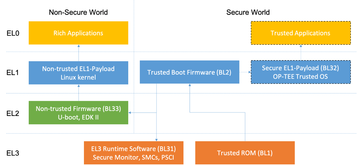
Let's break down the roles shown in the diagram:
- EL0 (User): Exists in both worlds. Normal World apps run at NS-EL0; Trusted Applications (TAs) run at S-EL0.
- EL1 (Kernel): Exists in both worlds. The Linux/Android kernel runs at NS-EL1; the TEE's kernel (like OP-TEE) runs at S-EL1.
- EL2 (Hypervisor): Primarily used in the Normal World for virtualization (e.g., KVM). Since ARMv8.4, a Secure EL2 also exists for virtualizing secure environments.
- EL3 (Secure Monitor): This is the linchpin of TrustZone. It runs in the Secure state only and has the highest privilege. Code running at EL3, known as the Secure Monitor, is responsible for:
- Handling world switches.
- Saving and restoring the context of one world before switching to the other.
- Passing messages between worlds.
A Normal World application can't just jump into the Secure World. It must execute an SMC (Secure Monitor Call) instruction, which generates an exception that is trapped by the Secure Monitor at EL3. The monitor then vets the request and passes control to the TEE in the Secure World.
3. Secure Boot: Building a Chain of Trust
TrustZone provides the environment for security, but it's useless if the trusted software itself can be tampered with. If an attacker could overwrite the TEE on the flash storage, they would own the Secure World.
Secure Boot solves this problem by creating a chain of trust. The process starts from a root of trust that is physically immutable, and each stage cryptographically verifies the next before executing it.
Watch this final clip from the NPTEL lecture, which explains the why and how of this chain.
#34 ARM Trustzone | Information Security 5 Secure Systems Engineering
This segment explains why Secure Boot is essential for a system using TrustZone and illustrates the concept of a 'chain of trust' where each boot component verifies the next.
Watch from 22:58 to 27:40. Focus on how the chain starts from a 'root of trust' and sequentially authenticates the bootloader, the secure OS, and finally the rich OS, ensuring the integrity of each component.
A Detailed Cortex-A Boot Chain Example
The industry-standard implementation of this boot process is ARM Trusted Firmware-A (TF-A). It defines a series of bootloader stages (BL stages). Here is a typical sequence for a Cortex-A SoC:
-
Stage 0: Boot ROM (Hardware Root of Trust)
- This is the very first code executed on power-on. It's burned into the silicon at the factory and is immutable.
- It contains a public key or a hash of a public key, often stored in One-Time Programmable (OTP) fuses. Once fuses are blown, they cannot be changed. This is the Hardware Root of Trust.
- Its job is to load the first mutable bootloader stage from flash and verify its digital signature against the key in its fuses. If verification fails, the boot halts.
-
Stage 1: Trusted Boot Firmware (TF-A BL2)
- This is the first stage loaded from mutable storage (e.g., eMMC, NAND flash).
- Its primary role is to initialize DRAM and then load the next stages: the EL3 runtime software (BL31), the Secure World OS (BL32, optional), and the Normal World bootloader (BL33).
- It verifies the signatures of all the images it loads before proceeding.
-
Stage 2: EL3 Runtime Software (TF-A BL31)
- This is the Secure Monitor code. After the initial boot is complete, BL31 remains resident in memory at EL3 for the lifetime of the system. It is responsible for handling
SMCcalls and managing world switches during runtime. - After setup, it passes control to the Normal World bootloader.
- This is the Secure Monitor code. After the initial boot is complete, BL31 remains resident in memory at EL3 for the lifetime of the system. It is responsible for handling
-
Stage 3: Normal World Bootloader (BL33)
- This is typically a standard bootloader like U-Boot or UEFI.
- It is now running in the Normal World (e.g., at EL1).
- Its job is to load the main operating system kernel (e.g., the Linux kernel
zImage), verify its signature, and jump to it.
-
Stage 4: OS Kernel and Beyond
- The Linux kernel boots. For further security, it can verify the integrity of its root filesystem using technologies like
dm-verity.
- The Linux kernel boots. For further security, it can verify the integrity of its root filesystem using technologies like
The LinkedIn article you read earlier provides a perfect text-based summary of this process. I highly recommend reviewing it now to solidify your understanding.
Security in Embedded Devices: RTOS and Linux on ARM
Let's revisit our main resource to get a clear, step-by-step breakdown of the secure boot chain and the role of the TF-A boot stages.
Please reread the sections under 'Secure Boot': 'What is Secure Boot?', 'Detailed Secure Boot Chain (Cortex-A Example)', 'ARM Trusted Firmware Boot Stages', and 'Secure Boot Key Storage'. This ties everything together.
Conclusion
This lesson covered the foundational security architecture of modern ARM SoCs. In an interview, being able to articulate this entire flow—from the hardware root of trust to the runtime isolation between worlds—demonstrates a deep understanding of system architecture.
Key Takeaways:
- ARM TrustZone provides hardware-enforced isolation by partitioning an SoC into a Secure World and a Normal World.
- The processor's security state is determined by the NS (Non-Secure) bit, which is propagated on the system bus and checked by TrustZone-aware peripherals.
- EL3 (Secure Monitor) is the highest privilege level and acts as the gatekeeper between the two worlds, handling world switches triggered by the
SMCinstruction or secure interrupts. - Secure Boot is essential to protect the integrity of the Secure World software. It uses a chain of trust to verify each stage of the boot process.
- This chain is anchored in an immutable Hardware Root of Trust—the Boot ROM and public key hashes stored in OTP fuses.
- ARM Trusted Firmware-A (TF-A) is the standard open-source implementation of the secure boot chain and the EL3 Secure Monitor.
Preview of the Next Module:
We have now concluded our deep dive into CPU and System Architecture. We've journeyed from instruction sets and pipelines to multi-core designs and secure system boot.
In the next module, "Embedded Data Structures and Algorithms," we will shift our focus from the hardware architecture to the software that runs on it. We'll start with a classic and critical low-level programming challenge: correctly implementing memcpy and memmove, paying special attention to the dangers of overlapping memory regions. This will bridge the gap between architectural knowledge and practical, efficient coding.