Hello! Welcome back to our study of wave optics.
In our last lesson, we uncovered the crucial rule of phase change upon reflection: a π radian (180°) phase shift occurs when light reflects from an optically denser medium. This insight is the final piece of the puzzle we need to understand the beautiful colours of soap bubbles and oil slicks.
Today, we will combine this rule with the concept of path difference to fully analyze the interference patterns in thin films. We will derive the conditions for constructive and destructive interference for different scenarios and then apply this framework to understand why films of varying thickness, like soap bubbles, display a spectrum of colours. As you requested, we'll anchor these concepts by tackling some NEET-style problems.
1. The Complete Picture: Path Difference and Phase Shifts
When light reflects from a thin film, two rays emerge and interfere: one from the top surface and one from the bottom. As we've learned, the total path difference, , between these two rays comes from two sources:
- Geometric Path Difference: The ray reflecting from the bottom surface travels an extra distance, which for near-normal incidence is .
- Phase Shifts on Reflection: A phase shift of (equivalent to a path difference of ) can occur at either surface.
Let's derive the interference conditions for the two main cases we introduced previously.
Case 1: Film in Air (e.g., Soap Bubble)
Consider a soap film () in air ().
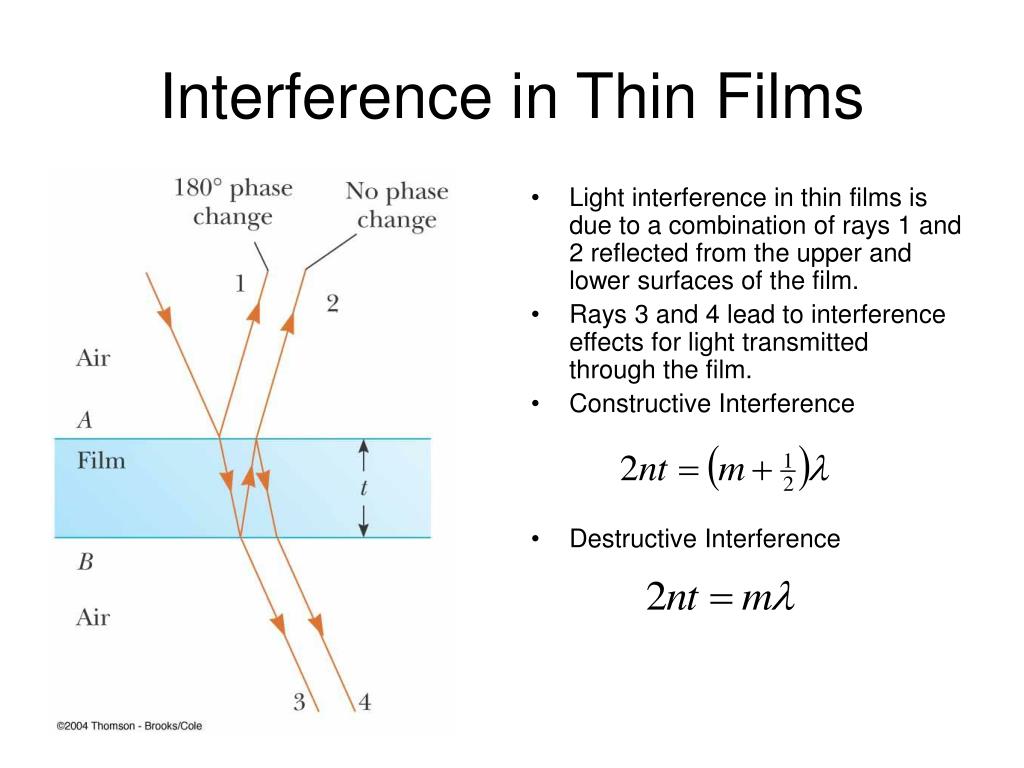
- Reflection 1 (Top surface): Occurs at the air film boundary. Since , this is a reflection off a denser medium. A phase shift of radians occurs.
- Reflection 2 (Bottom surface): Occurs at the film air boundary. Since , this is a reflection off a rarer medium. No phase shift occurs.
The net effect of the reflections is a relative phase difference of , which is equivalent to a path difference of .
The total effective path difference is:
(We use a minus sign here by convention, but whether it's plus or minus doesn't change the final conditions, as you'll see).
Now we apply the standard interference conditions:
- For Constructive Interference (Brightness):
- For Destructive Interference (Darkness):
If we let , where is another integer (1, 2, 3...), the condition simplifies. For simplicity, we usually write it as:
Notice something interesting: the conditions are the reverse of what we saw in the Young's double-slit experiment!
Case 2: Anti-Reflective Coating
Consider a coating () on glass () where .
- Reflection 1 (Top surface): Air Coating. Denser boundary phase shift.
- Reflection 2 (Bottom surface): Coating Glass. Denser boundary phase shift.
Here, both rays are phase-shifted by . Their relative phase difference due to reflection is zero.
The total effective path difference is simply the geometric path difference:
Now, the standard interference conditions apply directly:
- For Constructive Interference (Brightness):
- For Destructive Interference (Darkness):
This is the goal of an anti-reflective coating: to create destructive interference for visible light.
The most important takeaway for your exam preparation is this: Do not simply memorize the formulas. Always start by analyzing the phase shifts at both reflections to determine which set of conditions to apply.
2. Why Do We See Swirling Colors?

When white light (a mix of all wavelengths) illuminates a soap bubble, the film is not perfectly uniform. Gravity pulls the soapy water down, making the film wedge-shaped—thinner at the top and thicker at the bottom.
For a given thickness , the condition for constructive interference, , will be satisfied for a specific wavelength (a specific color).
- A slightly thicker part of the film will reflect a different color.
- As the bubble swirls and its thickness changes, the colors you see at any given point will shift.
A classic NEET conceptual question is: Why does a soap bubble appear black just before it bursts?
As the film becomes extremely thin (), the geometric path difference also approaches zero. The only remaining path difference is the from the reflection at the top surface. This path difference is the condition for destructive interference for all wavelengths. Since all colors are destructively interfered, no light is reflected, and the film appears black.
For a more detailed textual explanation of this phenomenon, you can review the following resource.
Understanding Thin Film Interference: Causes and Effects
This section from the Vedantu article 'Understanding Thin Film Interference' explains how the interplay between wavelength and varying film thickness produces rainbow-like patterns.
Please read the short section titled 'Rainbow Formation by Thin Films'. It provides a concise summary of how varying thickness leads to the separation of colors.
3. Application to NEET-Style Problems
Now let's bridge theory and application. The following video provides an excellent summary of the derivations and then applies them to solve several problems, which is exactly the kind of "vigorous" practice needed for NEET.
The video covers interference by both reflected light (what an observer sees looking at the film) and transmitted light (what an observer sees looking through the film). This is an important distinction.
Thin Film Interference | Booster Pack for JEE/NEET
This video from PW English Medium is designed for competitive exams. It will reinforce the derivations we just did and show you how to apply them systematically to solve problems involving both reflected and transmitted light.
Please watch the following segments in order: Theory Review (08:07 - 22:56): The instructor derives the conditions for both Case 2 (anti-reflective coating) and Case 1 (soap film). This will be a great reinforcement of what we just covered. Reflected Light Problem 1 (23:55 - 28:52): An oil film on glass. Pay attention to how the refractive indices are used to determine that this is a 'Case 2' scenario (Δx = 2μt). Reflected Light Problem 2 (28:52 - 35:34): A glass plate in air. This is a 'Case 1' scenario. Notice how the conditions for constructive interference are different from the first problem. Transmitted Light Problem (35:34 - 42:45): This is an important variation. For the primary transmitted rays, there are no reflection phase shifts involved. The path difference is simply due to the extra path traveled by one of the rays. Watch how the instructor sets up the path difference for destructive interference (a dark film).
After watching the video, let's solidify the approach to transmitted light.
Interference by Transmitted Light
When an observer looks at the light that passes through the film, they see the interference of two transmitted rays. The primary ray passes straight through. The second ray reflects twice internally before exiting.
- Key point: The phase shifts we discussed only happen on reflection. Refraction (transmission) never causes a phase shift.
- In the common case of a film in air, the two internal reflections (film air and film air) are both off a rarer medium, so there are no phase shifts there either.
- Therefore, for transmitted light, the path difference between the two main interfering rays is simply the geometric path difference from the extra travel distance of the second ray:
This means the conditions for transmitted light are the standard ones:
- Constructive (Brightness):
- Destructive (Darkness):
An interesting consequence is that the conditions for constructive interference in transmitted light are the same as for destructive interference in reflected light (for a film in air), and vice-versa. A film that appears dark by reflection will appear bright by transmission.
Test your understanding!
An anti-reflective coating () of thickness is applied to a camera lens (). We want to minimize the reflection of green light ().
- Write down the expression for the total path difference for reflected light.
- Write the condition for minimum reflection (destructive interference).
- Calculate the minimum non-zero thickness of the coating required.
Show answer
-
Path Difference: This is a "Case 2" scenario (). Reflections at both the top (air-coating) and bottom (coating-glass) surfaces are from denser media, so both have a phase shift. The net phase shift from reflection is zero. Therefore, .
-
Condition for Minimum Reflection: For destructive interference, the path difference must be a half-integer multiple of the wavelength:
-
Minimum Thickness: To find the minimum non-zero thickness, we set :
Plugging in the values:
Conclusion
Today we've built the complete model for thin-film interference. By carefully combining the geometric path difference with the phase shifts upon reflection, we can now confidently analyze any scenario.
Key Takeaways:
- The conditions for interference in thin films depend on the refractive indices of the film and surrounding media.
- Case 1 (e.g., Soap Bubble in Air): A net phase shift from reflections swaps the conditions:
- Constructive:
- Destructive:
- Case 2 (e.g., Anti-Reflective Coating): No net phase shift from reflections means the standard conditions apply:
- Constructive:
- Destructive:
- The colors in thin films arise because the constructive interference condition is met for different wavelengths at different film thicknesses.
- For transmitted light, the path difference is always , leading to the standard interference conditions.
Preview of the Next Lesson:
We have now covered all the core theory for interference in YDSE and thin films. The next lesson will be a dedicated, vigorous problem-solving session covering a variety of NEET-style questions on both topics, helping you build the speed and accuracy required for the exam.