Hello! Welcome to our next lesson in wave optics.
In our last session, we saw how introducing a thin transparent slab into a YDSE setup creates an optical path difference of , causing the entire fringe pattern to shift. This idea of an optical path is crucial, and we will build directly upon it today.
We are now moving on to another fascinating interference phenomenon: the vibrant, swirling colors you see on a soap bubble or a thin layer of oil on water. This is called thin-film interference. To understand it, we need to add one more critical piece to our physics toolkit.
Today's learning outcome is to explain the role of phase change upon reflection in thin-film interference. This is a fundamental concept that, when combined with the path difference, governs whether the light reflecting off a film interferes constructively or destructively.
1. The Missing Piece: Phase Change on Reflection
When a wave reflects from a boundary, its phase might change. For light waves, the rule is surprisingly simple and is best understood by an analogy to mechanical waves on a string.
- A wave on a string that reflects from a fixed end (a hard boundary) is inverted. This is a 180° or radian phase change.
- A wave on a string that reflects from a free end (an easy boundary) is not inverted. This is a 0° phase change.
Light behaves similarly. The "hardness" of the boundary is determined by the optical density (the refractive index, ) of the medium.
The Rule for Phase Change:
- When a light wave traveling in a medium of refractive index reflects off the surface of a medium with a higher refractive index (i.e., ), it undergoes a phase change of 180° ( radians). This is equivalent to having an extra path length of added to its journey.
- When a light wave reflects off a surface of a medium with a lower refractive index (i.e., ), there is no phase change.
The image below perfectly illustrates this rule. Notice that the refracted (transmitted) wave never undergoes a phase change.
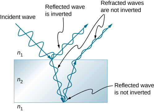
To see a more formal explanation of this phenomenon, please read the following section from a university physics text.
Chapter 37 Interference of Light Waves
This excerpt from the textbook 'Physics for Scientists and Engineers' by Serway and Jewett provides a concise and clear explanation of the phase change that occurs during reflection. It uses the excellent example of Lloyd's mirror to demonstrate why this phase change must exist.
Please read Section 37.5, titled 'Change of Phase Due to Reflection'. Focus on the general rule stated at the end of the section and the analogy with waves on a string summarized in Figure 37.16.
2. Applying the Rule to Thin Films
Now, let's see how this rule is the key to understanding thin-film interference. When light shines on a thin film, it reflects from two surfaces: the top surface and the bottom surface. The two reflected rays then interfere.
To find the total phase difference between them, we must consider two factors:
- Path Difference: The ray that reflects from the bottom surface travels an extra distance. For near-normal incidence, this path difference is approximately , where is the film's thickness and is its refractive index. This should feel familiar from our last lesson!
- Phase Change on Reflection: We must apply our new rule to both reflections and see what the net effect is.
The following video is from a popular channel for JEE/NEET preparation. It will walk you through the logic of combining these two factors.
Thin Film Interference | Booster Pack for JEE/NEET
This video from PW English Medium is tailored for competitive exams like NEET. It does an excellent job of explaining the core concepts and then immediately applying them to problem-solving frameworks.
Please watch the video in two parts: The Rule (05:07 - 08:07): This section introduces the rule of phase advancement of π (or path advancement of λ/2) upon reflection from a denser medium. This is the core concept for today's lesson. Scenario: Soap Bubble (18:08 - 21:00): This part applies the rule to a common and important case: a soap film in air. Pay close attention to how the instructor analyzes the reflections at the top (air-film) and bottom (film-air) surfaces to find the total path difference.
Case Study: Analyzing Reflections in a Thin Film
Let's consolidate what you just watched by breaking down the two most important scenarios.
Scenario 1: Soap Bubble in Air ()
This applies to a soap bubble or a film of oil floating on water where the oil's refractive index is greater than water's. Let's analyze a soap bubble in air ().

-
Ray 1 (reflects at top surface): The reflection happens at the Air Soap Film boundary. Since , the reflection is from an optically denser medium.
- Result: A phase shift occurs.
-
Ray 2 (reflects at bottom surface): This ray travels through the film and reflects at the Soap Film Air boundary. Since , the reflection is from an optically rarer medium.
- Result: No phase shift occurs.
-
Net Effect: One ray is phase-shifted, and the other is not. This means there is a net relative phase difference of radians (or ) between the two rays, just because of the reflections.
The total path difference is therefore:
Scenario 2: Anti-reflective Coating on Glass ()
This is used for coatings on camera lenses or eyeglasses. Let's assume Air (), Coating (), and Glass ().
-
Ray 1 (reflects at top surface): Reflection at the Air Coating boundary. This is a rarer-to-denser reflection.
- Result: A phase shift occurs.
-
Ray 2 (reflects at bottom surface): Reflection at the Coating Glass boundary. This is also a rarer-to-denser reflection ().
- Result: A phase shift occurs.
-
Net Effect: Both rays are phase-shifted by . Relative to each other, they are in phase. This means there is no net relative phase difference between the two rays from the reflections. The two phase shifts cancel each other out.
The total path difference is therefore just the geometric path difference:
This analysis is the heart of thin-film interference. Before you can write the conditions for constructive or destructive interference, you MUST first analyze the reflections to see if there is an extra path difference to account for.
Test your understanding!
Consider a thin film of water () on a flat piece of diamond (). Light from the air () shines on it.
- Does the ray reflecting from the top surface (air-water) undergo a phase shift?
- Does the ray reflecting from the bottom surface (water-diamond) undergo a phase shift?
- Is there a net relative phase difference between the two reflected rays due to the reflections?
Show answer
- Top surface (Air Water): Yes. The light reflects from a denser medium (), so there is a radian phase shift.
- Bottom surface (Water Diamond): Yes. The light reflects from a denser medium (), so there is another radian phase shift.
- Net Effect: No. Since both reflected rays undergo the same phase shift, their relative phase difference due to reflection is zero. This situation is like the anti-reflective coating. The total path difference will be just .
Conclusion
In this lesson, we've isolated and understood the crucial role of phase changes in thin-film interference. This concept is what distinguishes this topic from the simpler interference in YDSE.
Key Takeaways:
- Light undergoes a 180° () phase change upon reflection from an optically denser medium ().
- No phase change occurs upon reflection from an optically rarer medium.
- In thin-film interference, you must analyze the reflections at both the top and bottom surfaces to determine the net relative phase change.
- This reflection-induced phase change (which is either 0 or ) must be combined with the geometric path difference () to find the total path difference that dictates the final interference pattern.
Preview of the Next Lesson:
We now have all the necessary components! In our next lesson, we will analyze interference patterns in thin films in detail. We will combine the geometric path difference and the phase change on reflection to write the definitive equations for constructive and destructive interference. We will then apply these equations to solve a variety of NEET-style problems, such as finding the thickness of a film that reflects a certain color or the colors that are eliminated from reflection.