Hello! Welcome to the next lesson in our journey through wave optics.
In the last lesson, we did the heavy lifting of deriving the mathematical conditions for constructive and destructive interference. We found that everything depends on the path difference, , between two coherent waves.
- Constructive Interference:
- Destructive Interference:
Today, we will apply these fundamental conditions to one of the most important experiments in physics: Young's Double-Slit Experiment (YDSE). Our goal is to analyze the geometry of this experiment to calculate the exact positions of the bright and dark fringes on a screen, and the spacing between them, known as the fringe width. Mastering YDSE is absolutely critical for your NEET preparation, as it's a favorite topic for numerical problems.
1. Visualizing the Experiment
Before we jump into equations, let's build a mental picture of what's happening. In YDSE, light from a single source passes through two very narrow, closely spaced slits. These two slits then act as two perfectly coherent sources. The waves spread out from each slit and interfere, creating a pattern of alternating bright and dark bands (fringes) on a screen placed some distance away.
To see this in action, the following video provides an excellent animated simulation.
Wave Optics 02 | Young’s Double Slit Experiment | Pure English | 12th JEE/NEET/CUET
This clip from PW English Medium shows a computer simulation of YDSE, helping you visualize how the interference pattern is formed from the two slits.
Watch the segment from 04:55 to 08:58. Pay attention to how the plane wavefronts become spherical wavefronts after passing through the slits, and how their overlap creates the distinct bright and dark fringes on the screen.
2. The Geometry of YDSE and Path Difference
Now, let's translate this physical setup into a diagram we can analyze. This is the crucial step where we connect the geometry of the experiment to the path difference, .
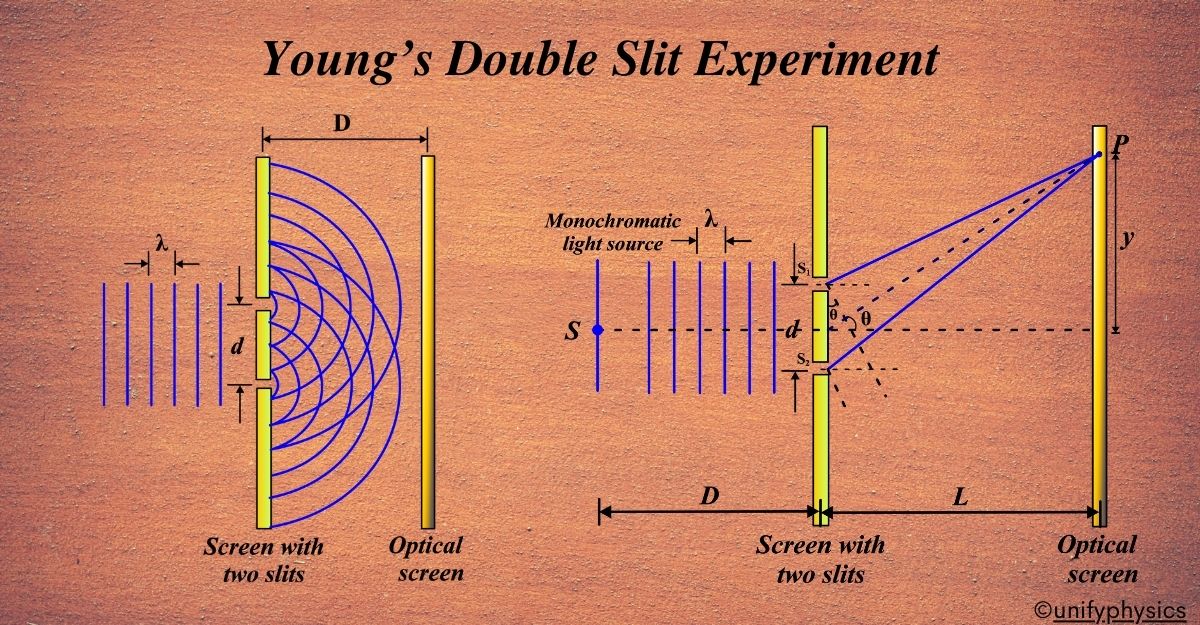
Here are the key parameters:
- d: The distance between the two slits (S1 and S2).
- D: The distance from the slits to the screen.
- : The wavelength of the monochromatic light.
- y: The vertical position of a point P on the screen, measured from the center.
Our first task is to find the path difference in terms of these parameters. In a typical YDSE setup, the distance to the screen D is much, much larger than the slit separation d (). This allows for a crucial mathematical simplification known as the small angle approximation.
The derivation shows that for a point P at position y on the screen, the path difference is given by:
This simple equation is the bridge between the physical layout of the experiment and the condition for interference.
For a detailed walkthrough of the geometry and the derivation of this path difference formula, please study the following material.
Young's Double Slit Experiment Derivation Explained
This article from Vedantu provides a concise, step-by-step derivation for the YDSE formulas, which is excellent for exam preparation.
Read the sections 'Physical Setup and Principle...' and 'Complete Derivation...'. Focus on 'Step 1' to see how the expression Δx = d sin θ is obtained and then approximated to Δx = dy/L (they use L instead of D).
3. Calculating Fringe Position and Fringe Width
Now that we have our expression for path difference, the rest is straightforward. We simply substitute it into the conditions for interference that we learned in the last lesson.
Position of Bright Fringes (Maxima)
For constructive interference, we need , where
Solving for , we get the position of the n-th bright fringe:
- For , we get . This is the central bright fringe.
- For , we get the first bright fringe at .
- For , we get the second bright fringe at , and so on.
Position of Dark Fringes (Minima)
For destructive interference, we need , where
Solving for , we get the position of the n-th dark fringe:
- For , we get the first dark fringe at .
- For , we get the second dark fringe at , and so on.
Fringe Width ()
The fringe width is defined as the distance between two consecutive bright fringes (or two consecutive dark fringes). Let's calculate it for the bright fringes:
Notice that the fringe width is independent of . This means that, under the small angle approximation, all the fringes are equally spaced.
The following video provides a clear derivation of these three essential formulas.
Wave Optics 02 | Young’s Double Slit Experiment | Pure English | 12th JEE/NEET/CUET
Let's return to the PW English Medium video to see the derivation of the formulas for the position of bright and dark fringes, and the fringe width.
Watch the segment from 43:16 to 46:46. This part directly derives the expressions for the location of bright and dark fringes, and then calculates the fringe width, β.
4. Problem Solving for NEET
As you requested, we will now focus vigorously on applying these formulas to solve numerical problems typical of the NEET exam.
Problem 1: Direct Calculation
This is the most basic type of YDSE problem where you are given the experimental parameters and asked to find the fringe properties.
Wave Optics 02 | Young’s Double Slit Experiment | Pure English | 12th JEE/NEET/CUET
The following video segment solves a problem where you're given λ, d, and D, and asked to calculate the fringe width and the position of the first dark and second bright fringes.
Watch the solved example from 47:19 to 51:14. Follow the calculations carefully. Note how the formulas for y_bright, y_dark, and β are applied directly.
Test your understanding!
In a YDSE setup, the distance between the slits is 0.28 mm and the screen is placed 1.4 m away. The distance between the central bright fringe and the fourth bright fringe is measured to be 1.2 cm. Determine the wavelength of light used.
Show answer
We are given:
- Slit separation,
- Screen distance,
- The position of the fourth bright fringe,
The position of the n-th bright fringe is given by .
For the fourth bright fringe, .
We need to find the wavelength . Let's rearrange the formula:
Now, substitute the values:
Converting to nanometers (1 nm = 10⁻⁹ m) or Angstroms (1 Å = 10⁻¹⁰ m):
The wavelength of the light used is 600 nm.
Problem 2: Changing the Medium
A common variation involves immersing the entire experimental setup in a transparent medium, like water.
The key thing to remember is that the wavelength of light changes when it enters a medium with refractive index . The new wavelength is . How does this affect the fringe width?
The new fringe width will be:
The fringe width decreases by a factor of the refractive index.
Wave Optics 02 | Young’s Double Slit Experiment | Pure English | 12th JEE/NEET/CUET
Let's see how this is applied in a problem. This segment shows how to calculate the new fringe width when the YDSE setup is immersed in water.
Watch the solved problem from 51:14 to 54:00. The key insight is the change in wavelength inside the medium.
Problem 3: Coincidence of Fringes
Another classic problem type involves two separate YDSEs performed with different wavelengths, where a fringe from one pattern coincides (overlaps) with a fringe from the other.
The trick here is to set their position equations equal to each other. For example, if the n-th bright fringe of coincides with the m-th bright fringe of , you would write:
Wave Optics 02 | Young’s Double Slit Experiment | Pure English | 12th JEE/NEET/CUET
This video segment tackles a slightly more complex coincidence problem: a bright fringe from one wavelength merges with a dark fringe from another.
Watch the final problem from 54:00 to 57:16. See how the position formula for a bright fringe is set equal to the position formula for a dark fringe to find the relationship between the wavelengths.
Conclusion
Today, we have thoroughly analyzed Young's Double-Slit Experiment, the cornerstone of wave optics. By combining the geometry of the setup with the conditions for interference, we derived the essential formulas for solving a wide range of problems.
Key Takeaways:
- The path difference at a point
yon the screen is . - The position of the n-th bright fringe is .
- The position of the n-th dark fringe is .
- The fringe width, , is constant and given by .
- When the setup is in a medium of refractive index , the fringe width becomes .
Preview of the Next Lesson:
We will continue our analysis of YDSE by investigating a very common scenario in exams: what happens to the interference pattern if we introduce a thin, transparent sheet (like glass or mica) into the path of one of the beams? This will cause the entire fringe pattern to shift, and our next goal will be to calculate this fringe shift.