Hello! Welcome to the third lesson on LLC resonant converters.
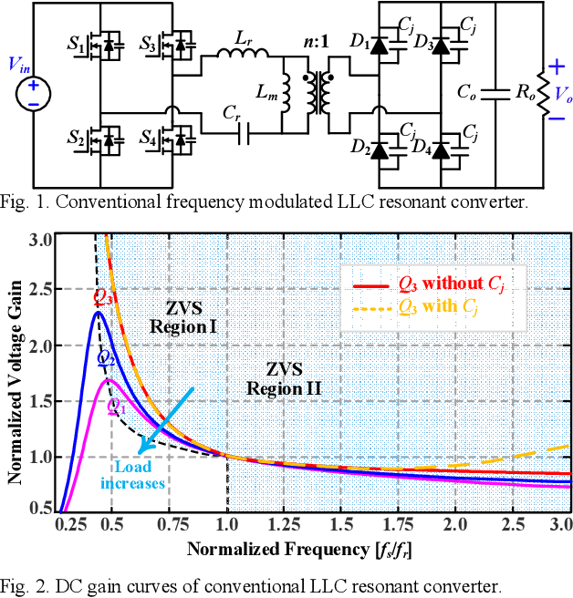
In our last session, we dissected the LLC gain curves and established how the converter's gain is a function of the switching frequency, the load (represented by Q), and the inductance ratio (m). We saw that by adjusting the switching frequency, we can move along these curves to get the gain we need.
Today, we will connect that theory to practice. Our learning goal is to explain how frequency modulation is used for output regulation and its impact on efficiency. We'll explore the different operating modes this creates and see how a controller implements this strategy to balance performance and efficiency. By the end of this lesson, you'll understand the direct link between switching frequency and a converter's efficiency profile.
The Three Modes of Frequency-Modulated Operation
As we learned, the controller's primary job is to adjust the switching frequency () to keep the output voltage constant as input voltage and load change. This operation is typically centered around the resonant frequency (), leading to three distinct modes, each with a different impact on the converter's behavior and efficiency.
The following video from Infineon provides an excellent overview of these three modes, complete with waveform diagrams and explanations of the associated losses.
Developing Clean Efficient Power with LLC Resonant Converters with Infineon
To understand how frequency changes affect efficiency, we need to look at the converter's operation at, above, and below its resonant frequency. This video explains these three modes in detail.
Please watch the segment from 10:11 to 14:19. Focus on understanding the key characteristics of each mode: At Resonance: Why is this the most efficient point? Above Resonance: What happens to the waveforms and losses? Below Resonance: What is 'circulating current' and how does it affect efficiency?
To solidify these concepts, the application note we've used previously provides a very clear summary table. This is a great resource to have on hand when reviewing designs.
Resonant LLC Converter: Operation and Design
The Infineon application note provides a concise written summary of the three operating modes, which will reinforce what you just saw in the video.
Read the first part of section '2.2 Modes of Operation', focusing on Table 1. This table is a powerful reference that summarizes the conditions and consequences of operating in each of the three frequency modes.
Let's distill the key characteristics and their impact on efficiency:
-
At Resonant Frequency ()
- Purpose: The resonant tank gain is 1. This is the "sweet spot" of operation. Designers typically choose the transformer turns ratio so the converter operates here at its nominal input voltage and full load.
- Efficiency Impact: Highest efficiency. The resonant inductor () and capacitor () effectively cancel each other out. The current delivered to the output is almost perfectly sinusoidal, and power transfer is maximized. The secondary rectifier diodes naturally switch off at zero current (ZCS), eliminating their switching losses.
-
Above Resonant Frequency ()
- Purpose: The gain is less than 1 (buck mode). This mode is used when the input voltage is higher than nominal or the load is lighter, requiring less gain.
- Efficiency Impact: Good efficiency, but decreases as frequency rises. The primary-side MOSFETs still achieve ZVS. However, the switching period ends before the resonant cycle completes. This can cause the secondary rectifier diodes to turn off abruptly while current is still flowing (hard commutation), re-introducing switching losses on the secondary side. Furthermore, higher switching frequencies inherently increase gate-drive losses and other frequency-dependent losses in the MOSFETs.
-
Below Resonant Frequency ()
- Purpose: The gain is greater than 1 (boost mode). This is necessary when the input voltage drops below nominal.
- Efficiency Impact: Efficiency drops due to circulating currents. In this mode, the resonant current cycle finishes before the switching period ends. During this "dead time," the magnetizing inductance () effectively enters resonance with the tank. This creates a significant "circulating current" that flows through the primary-side MOSFETs and resonant components but does not transfer power to the output. This extra current increases conduction losses () significantly, making this the least efficient of the three modes, even though ZVS/ZCS are maintained.
Practical Efficiency Data
Theory is one thing, but seeing real-world data drives the point home. The design example in the Infineon application note includes measured efficiency across different input voltages and loads. This forces the converter to use frequency modulation, and the results align perfectly with our theory.
Resonant LLC Converter: Operation and Design
Let's look at some real-world efficiency measurements from a prototype LLC converter. This data clearly shows how efficiency changes as the converter's operating point is modulated by frequency.
Go to section '5.3 Experimental Waveforms and Efficiency'. Examine Table 6 and the corresponding graph in Figure 5.7. Notice how the efficiency changes with the input voltage. For a given output power (e.g., 250W), where is the efficiency highest? Where is it lowest? How does this correspond to the three operating modes we just discussed?
From the data, you can see that for a 250W load, the efficiency peaks at 97.6% with a 33V input. As the input voltage drops to 18V (requiring boost mode, ), efficiency falls to 96.2%. This drop is primarily due to the increased conduction losses from circulating currents. This demonstrates the real-world cost of operating away from the ideal resonant point.
The Controller's Strategy
An LLC controller IC is the brain behind this operation. It's not just a simple oscillator; it's a sophisticated state machine designed to manage the frequency modulation safely and efficiently.
This next video segment explores the specific features an LLC controller needs, such as setting frequency limits and handling light-load conditions.
Developing Clean Efficient Power with LLC Resonant Converters with Infineon
Now that we know the 'what' and 'why' of frequency modulation, let's look at the 'how'. This video explains the essential features of a dedicated LLC controller IC.
Watch the two segments from 20:36 to 24:30 and 29:04 to 30:12. Pay attention to these key control functions: Setting minimum and maximum switching frequencies. Using high frequency for protection (like over-current). Using 'burst mode' for high efficiency at very light loads.
Key Control Functions:
-
Setting Frequency Limits: A designer programs the controller with a minimum and maximum frequency.
- Minimum Frequency (): This is a critical safety feature. As we saw in the gain curves, at very low frequencies, the converter can enter the "capacitive region" where ZVS is lost, leading to destructive hard switching. is set to keep the operating point safely in the inductive (ZVS) region across all load conditions.
- Maximum Frequency (): This is an efficiency limit. As frequency rises, switching-related losses increase. prevents the controller from pushing the frequency to a point of diminishing returns.
-
Burst Mode (or Pulse Skipping): At very light loads, the controller would need to drive the frequency extremely high to lower the gain sufficiently. This is inefficient. Instead, the controller enters "burst mode": it operates for a few cycles at an efficient frequency, then pauses, effectively delivering a low average power while minimizing switching losses.
-
Primary-Side ZCS Detection: Some older controllers could get "stuck" if they accidentally entered the capacitive region. Modern controllers have a feature to detect this condition (which corresponds to Zero Current Switching on the primary side) and automatically increase the frequency to push the converter back into the safe ZVS zone.
Improving ZVS and efficiency in LLC converters
This Texas Instruments application note provides another perspective on the importance of avoiding the capacitive (primary ZCS) region and how modern controllers handle it.
Read 'Tip 6, Avoid ZCS on primary switch node (Vsw)'. This section concisely explains why operating in this region is problematic and contrasts how older vs. newer controllers manage the risk.
Conclusion
You now have a complete picture of how an LLC converter uses frequency modulation for regulation and the direct consequences this has for efficiency. When you review a PCB, you can apply this knowledge by examining the LLC controller and its programming components to understand the intended operating range and efficiency trade-offs.
Key Takeaways:
- LLC converters regulate their output by modulating the switching frequency () around the resonant frequency ().
- At Resonance (): Unity gain, highest efficiency, ZCS on secondary rectifiers. This is the optimal design point.
- Above Resonance (): Gain < 1 (buck). Used for high input voltage. Efficiency is reduced by higher switching losses and potential loss of secondary-side ZCS.
- Below Resonance (): Gain > 1 (boost). Used for low input voltage. Efficiency is significantly reduced by high circulating currents causing large conduction losses.
- Controllers manage this process by operating within a programmed frequency range (, ) and using special modes like "burst mode" to maintain high efficiency at light loads.
In our next and final lesson on LLC converters, we will step back and compare its advantages and limitations against another major ZVS topology: the Phase-Shifted Full-Bridge converter. This will help you understand the broader context of where and why each topology is chosen.