Hello! Welcome to the third lesson in our module on practical ZVS design and optimization.
In our last two lessons, we identified the key component parameters for ZVS and explored how to optimize dead-time and resonant parameters to achieve it. You learned that achieving ZVS is a careful balancing act. Now, we'll answer a critical question: If we successfully achieve ZVS, where does the rest of the energy go?
This lesson addresses the learning outcome: Analyze the primary loss mechanisms that persist in ZVS converters, such as conduction and magnetic losses. While ZVS is a powerful technique for improving efficiency, it doesn't create a perfectly lossless converter. Understanding the remaining loss sources is essential for a complete efficiency analysis and for making informed trade-offs during a design review.
1. ZVS is Not Lossless: A Realistic View
Zero Voltage Switching is more accurately "Zero Voltage Turn-On". It masterfully eliminates the loss associated with discharging the MOSFET's output capacitance () through the channel during turn-on. However, other loss mechanisms remain.

Let's break down these remaining losses, starting with those still related to the switching transition.
The Other Half of the Switching Cycle
The following resource explains two often-overlooked losses that persist even with perfect ZVS turn-on.
Beware of Zero Voltage Switching - Mouser Electronics
This document from Mouser Electronics, titled 'Beware of Zero Voltage Switching', provides a concise and clear explanation of the fundamental limitations of ZVS.
Please read the first page of this document. Focus on these key ideas: The section explaining that ZVS only reduces turn-on losses, while turn-off crossover losses still occur. The excellent explanation of the two halves of the C_{oss} energy loss. Understand why the charging half of the energy (\frac{1}{2}CV^2) is still lost during turn-off. The discussion on body diode conduction and its associated efficiency penalty, even when dead-time is optimized.
To summarize the key points from the reading:
-
Turn-Off Crossover Loss: The MOSFET still turns off while it is conducting current. For a brief moment as the channel's resistance increases and the voltage across it rises, there is a period of simultaneous voltage and current, leading to power loss (). ZVS does not address this.
-
Charging Loss: This is a more subtle but important loss. The total energy associated with a capacitor being charged and discharged to a voltage is .
- Discharging: ZVS saves the of energy stored in by recycling it to the load instead of dissipating it as heat. This is the primary benefit of ZVS.
- Charging: However, when the MOSFET turns off, the circuit must provide of energy to charge back up to the blocking voltage. This energy is drawn from the source and is dissipated as a loss. This loss is particularly significant in high-voltage converters due to the term.
-
Body Diode Losses: As we saw in the previous lesson, achieving ZVS requires the body diode to conduct for a short period. This introduces two loss components:
- Conduction Loss: For the duration of the dead-time, power is lost due to the diode's forward voltage drop ().
- Reverse Recovery Loss: In silicon MOSFETs, this stored charge () must be removed, which causes a spike of recovery current and significant loss.
2. Conduction Losses: The Unavoidable Toll
Once the switch is fully on, the primary loss mechanism is simple conduction loss, often described by . In a ZVS converter, this occurs in the MOSFETs and the magnetic component windings.
MOSFET On-Resistance ()
When a MOSFET is on, it acts like a small resistor. The power dissipated is:
In resonant converters like the LLC, the RMS current () flowing through the primary switches can be higher than in an equivalent hard-switched converter due to the circulating resonant energy. This makes selecting a MOSFET with low crucial for minimizing conduction losses, even though switching losses are reduced.
AC Winding Losses: Skin and Proximity Effects
This is arguably the most critical and complex loss mechanism to understand for high-frequency converters. The windings in your transformer and inductor are not perfect conductors, especially when dealing with the high-frequency currents found in ZVS circuits. Their effective resistance increases dramatically due to two phenomena:
- Skin Effect: At high frequencies, AC current tends to flow only on the outer surface (the "skin") of a conductor, effectively reducing its cross-sectional area and increasing its resistance.
- Proximity Effect: The magnetic field from an adjacent conductor induces eddy currents in its neighbor. These eddy currents cause the current distribution to become even more non-uniform, further increasing the effective resistance. This effect is dominant in multi-layer transformer windings.
The following video provides a fantastic, intuitive explanation of these effects and why they matter.
Skin and proximity effects: an intuitive explanation of Dowell’s loss model
To understand where AC conduction losses in magnetics come from, let's watch an excellent intuitive explanation by Prof. Sam Ben-Yaakov. This will clarify the skin effect and the proximity effect.
Please watch the following segments: 2:31 - 6:07: For a conceptual explanation of the skin effect and the proximity effect. Focus on how they reduce the usable cross-sectional area of the wire for AC currents. 26:44 - 39:14: This covers practical solutions (like Litz wire and planar magnetics) and provides a summary. This is directly relevant for evaluating component choices during a PCB review.
The crucial takeaway for your goal of reviewing PCBs is this: using a thick, solid wire for a high-frequency transformer is often a poor choice. The AC resistance () can be many times higher than the DC resistance (), leading to massive conduction losses. This is why you will see specialized windings in high-performance supplies:
- Litz Wire: A bundle of individually insulated, thin wire strands. This forces the current to share among all strands, dramatically reducing skin and proximity effects.
- Planar Magnetics / Thin Foil Windings: Using flat traces on a PCB or thin copper foils for windings. The thin vertical profile minimizes the area for eddy currents to form.
Test your understanding!
You are reviewing a 500W, 200 kHz LLC converter design. You notice the main transformer is wound with a single, thick, solid copper wire. What is the most likely performance issue this will cause, and what alternative would you suggest?
Show answer
The most likely issue is extremely high winding conduction loss in the transformer. At 200 kHz, the skin effect will be significant, but the proximity effect from adjacent winding layers will be even more severe, causing the AC resistance to be many times the DC resistance. This will lead to the transformer overheating and poor overall converter efficiency.
A much better alternative would be to use Litz wire of an equivalent cross-sectional area. Another option could be to use thin copper foil windings if the transformer geometry allows. Both solutions are designed to mitigate AC winding losses at high frequencies.
3. Magnetic Core Losses
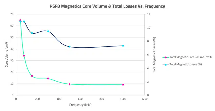
The ferrite cores of transformers and inductors are not lossless either. As the magnetic field rapidly cycles, energy is dissipated as heat within the core material itself. This loss has two primary sources:
- Hysteresis Loss: It takes energy to repeatedly flip the magnetic domains inside the ferrite material. This energy is lost as heat in every AC cycle.
- Eddy Current Loss: The changing magnetic flux induces small electrical currents within the conductive ferrite core itself. These "eddy currents" dissipate power according to .
Core loss is heavily dependent on switching frequency, the peak AC flux density swing (), and temperature. Manufacturers provide data sheets that allow designers to estimate this loss.
4. Putting It All Together: A Loss Budget
A complete analysis involves estimating each of these loss components to create a "loss budget." Let's look at a practical example.
Maximizing efficiency of your LLC power stage
This presentation from Texas Instruments, 'Maximizing efficiency of your LLC power stage', provides a worked example of calculating the major losses in an LLC converter.
Please scan through the slides titled 'Component selection & losses' for the HV MOSFET, SR MOSFET, transformer, and resonant inductor. You don't need to follow every number, but observe the types of losses being calculated: HV MOSFET: Note the calculation for P_CondHV (conduction) and P_SwHV (turn-off switching). SR MOSFET: Note the P_condSR (conduction) and P_diodeSR (body diode) loss components. Transformer: See the P_transFE (core loss, 'FE' for Ferrite) and P_transcu (winding loss, 'cu' for Copper). Resonant Inductor: Similarly, note the core and conduction losses. Finally, look at the 'Total losses' slide, which summarizes everything in a budget.
As you can see, a full analysis considers a wide range of factors. Here is a summary of the primary loss mechanisms that persist in a ZVS converter:
| Loss Category | Specific Source | Key Dependencies |
|---|---|---|
| Switching Losses | Turn-Off Crossover Loss | Current at turn-off, turn-off speed |
| Charging Loss | , Frequency, | |
| Body Diode Conduction & Recovery | Dead-time, , , | |
| Gate Drive Loss | , Gate Voltage, Frequency | |
| Conduction Losses | MOSFET Loss | RMS Current, |
| Winding Loss (Skin/Proximity) | RMS Current, Frequency, Winding Geometry | |
| Magnetic Losses | Core Hysteresis & Eddy Current | Frequency, Flux Swing (), Core Material, Volume |
Conclusion
You now have a comprehensive map of where the energy goes in a real-world ZVS converter. Eliminating the capacitive turn-on loss is a huge step, but achieving high efficiency requires a holistic approach to minimizing all the remaining loss components.
Key Takeaways:
- ZVS is not a "magic bullet"; it primarily eliminates capacitive turn-on loss. Significant losses remain, including turn-off loss and charging loss.
- Conduction losses () in both the MOSFETs and magnetic windings are a major contributor. At high frequencies, AC winding resistance due to skin and proximity effects can dominate, making winding strategy (e.g., Litz wire) critical.
- Magnetic core losses (hysteresis and eddy currents) are a fundamental trade-off with size and frequency.
- Optimizing a converter is about managing a loss budget that accounts for all of these competing factors.
In our next lesson, we will use this knowledge to compare different ZVS topologies (Active Clamp Flyback, Phase-Shifted Full-Bridge, LLC). We will analyze how their unique structures cause them to excel or struggle in managing these various loss mechanisms, helping you understand which topology is best suited for a given application.