Hello! Welcome back to our study of the Phase-Shifted Full-Bridge (PSFB) converter.
In our last lesson, we discovered the key asymmetry of the PSFB: the lagging leg achieves Zero Voltage Switching (ZVS) easily due to high load current, while the leading leg struggles, especially at light loads. This happens because the energy available for the ZVS transition depends on the primary current at the moment of switching.
Today, we will dig deeper into this relationship. Our learning outcome is to identify the role of leakage/series inductance and load current in achieving full ZVS operation. We will see precisely how these two parameters dictate the ZVS performance of the converter and explore the critical engineering trade-offs they create. Understanding this is essential for diagnosing efficiency problems and evaluating the robustness of a PSFB design.
The Fundamental Energy Balance for ZVS
At its core, achieving ZVS is an energy game. You need enough stored inductive energy to overcome the capacitive energy stored in the MOSFETs' parasitic output capacitances ().
The condition for successful ZVS is:
Inductive Energy Stored > Capacitive Energy to be Discharged
Mathematically, this is expressed as:
Let's break down these terms:
- : This is the total resonant inductance in the primary circuit. It's the sum of the transformer's inherent leakage inductance and any external inductor added in series.
- : This is the primary current flowing through at the exact moment a switching transition begins.
- : This is the effective capacitance of the switching node. It's primarily the sum of the of the two MOSFETs in the switching leg, plus any parasitic capacitance from the transformer winding itself.
- : This is the DC input voltage to the bridge.
The following reading from a Texas Instruments application note provides a more formal look at these energy components and how they fit into the resonant transition.
Phase Shifted Full Bridge, Zero Voltage Transition Design ...
This application note, 'Phase Shifted Full Bridge, Zero Voltage Transition Design,' provides the foundational equations for ZVS. We will focus on the sections defining the energy requirements.
Please read the sections titled 'RESONANT TANK CONSIDERATIONS' (page 12-13) and 'STORED INDUCTIVE ENERGY' (page 14). Focus on how the stored inductive energy in L_R must be greater than the capacitive energy in C_R to complete the transition. Note the equations provided for both W(C_R) and W(L_R).
This energy balance is the key to everything that follows. ZVS is achieved if the left side of the equation is larger than the right side. Since and are relatively fixed for a given design, our ability to achieve ZVS depends entirely on the values of and . Let's examine each.
The Role of Load Current ()
The primary current, , is directly proportional to the current being delivered to the load. This is the most dynamic variable in the ZVS equation and the reason why ZVS performance is load-dependent.
- Heavy Load: A heavy load demands high current. This results in a large , which in turn provides ample inductive energy (). ZVS is easily achieved on both legs.
- Light Load: As the load decreases, drops significantly. The stored inductive energy dwindles. At some point, it becomes insufficient to fully discharge the node capacitance within the dead-time, and the switch turns on "hot," resulting in hard-switching losses.
This is why PSFB converters have a minimum load requirement to maintain ZVS, especially on the leading leg where the current is lowest.
Let's watch a short video that explains this concept intuitively.
An intuitive introduction to Phase Shift Full Bridge (PSFB) converters
In this clip from his 'An intuitive introduction to Phase Shift Full Bridge (PSFB) converters' video, Dr. Sam Ben-Yaakov explains why ZVS is inevitably lost at low power levels.
Watch from 11:17 to 12:55. Pay attention to the core argument: the energy required to charge the capacitors comes from the inductor. If the power, and therefore the current, is too low, there won't be enough energy to complete the transition.
We can rearrange the energy balance equation to solve for the minimum primary current required to guarantee ZVS:
This equation is a powerful design tool. When reviewing a circuit, you can see that if the current available at the leading leg transition (which is a function of light-load current and magnetizing current) falls below this calculated , the converter will lose its soft-switching benefits and its efficiency will drop.
The TI application note we looked at earlier summarizes this derivation nicely. Section 'MINIMUM PRIMARY CURRENT' on page 15 of the "Phase Shifted Full Bridge, Zero Voltage Transition Design..." document (ID: LINK) presents this exact formula.
The Double-Edged Sword: Resonant Inductance ()
Looking at the ZVS equations, it seems like we have an easy fix for light-load efficiency: just increase the resonant inductance, . A larger inductor stores more energy for a given current, making ZVS possible at lighter loads.
So, why not use a very large inductor and guarantee ZVS across the entire load range? This is where the engineering trade-offs come in. A large series inductance has significant downsides.
Trade-off 1: Duty Cycle Loss
The primary job of the PSFB is to apply a square-wave voltage to the transformer. However, the series inductor is in the path. During the dead-time and the freewheeling phase, the primary current must reverse direction. A larger inductor has more inertia (), meaning it takes longer for the current to change direction. While the current is ramping, the full voltage is not applied across the transformer primary. This "lost" time reduces the effective duty cycle seen by the output, limiting the converter's ability to regulate the output voltage, especially at low input voltages.
The following video explains this "duty cycle loss" effect very clearly.
Transformer Design Considerations for Full Bridge Phase Shift | Frenetic @ IEEE-PELS
This clip from a Frenetic presentation at an IEEE event illustrates how leakage inductance causes a loss in the effective duty cycle.
Watch from 06:25 to 07:55. Notice in the waveforms how the voltage applied to the transformer (VSEC) has a narrower pulse width than the voltage generated by the bridge (VAB). The video explains that this is due to the leakage inductance, and the effect is dependent on both the inductance value and the load current.
Trade-off 2: Implementation & Efficiency
The resonant inductor can be the transformer's own leakage inductance or a separate, external component. This choice has practical consequences.
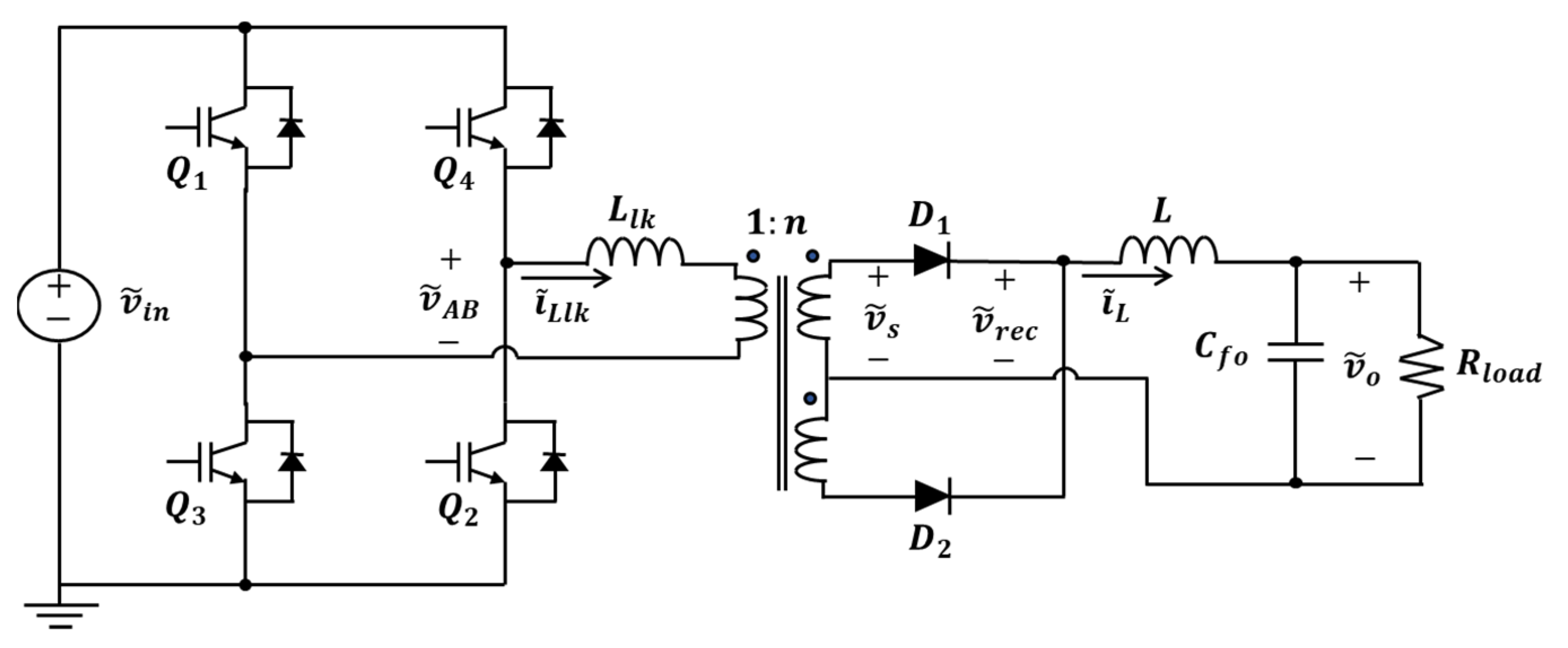
To gain more insight into the design choices and their consequences, let's watch another segment from the Frenetic video.
Transformer Design Considerations for Full Bridge Phase Shift | Frenetic @ IEEE-PELS
This excellent segment discusses the practical challenge of selecting the resonant inductance value. It weighs the pros and cons of using the transformer's leakage inductance versus adding an external inductor.
Please watch from 20:35 to 24:59. This is a practical and detailed discussion. Focus on these key points: Why it's difficult to control a transformer's leakage inductance precisely. How high leakage inductance can hurt transformer efficiency (poor coupling) and cause voltage spikes on the secondary side. The example showing how different winding arrangements dramatically change the leakage inductance. The final conclusion that it's often better to design a high-efficiency (low leakage) transformer and add a precise external inductor.
As the video explained, relying on leakage inductance alone is a compromise. While it saves a component, it's hard to manufacture consistently and can lead to a less efficient transformer design. Using a smaller, optimized external inductor provides predictable ZVS performance without compromising the transformer's primary function of efficient power transfer. When reviewing a PCB, the presence of a small inductor in series with the transformer primary is a strong clue that the designers have explicitly engineered the ZVS characteristic.
Test your understanding!
You are reviewing a PSFB design intended for high power. You notice the designer has specified a transformer with unusually high leakage inductance to ensure ZVS down to very light loads. What potential negative consequence should you immediately be concerned about?
a) The converter will have very high conduction losses at full load.
b) The converter may not be able to maintain its output voltage at low input line voltage and full load.
c) The converter will lose ZVS on the lagging leg.
Show answer
The correct answer is b) The converter may not be able to maintain its output voltage at low input line voltage and full load.
A very high leakage inductance will cause significant duty cycle loss. At full load and minimum input voltage, the converter needs the maximum possible duty cycle to transfer enough energy. The large duty cycle loss from the high inductance might prevent it from achieving this, causing the output voltage to "droop" or fall out of regulation.
Conclusion
Today we've connected the conceptual understanding of ZVS to the two most important design parameters that control it. The interplay between load current and series inductance defines the performance of a PSFB converter.
Key Takeaways:
- ZVS is an Energy Balance: Successful ZVS depends on the stored inductive energy () being greater than the parasitic capacitive energy ().
- Load Current is King: The primary current () is directly tied to the load. As the load decreases, falls, and the converter eventually loses ZVS. This defines a minimum operating load for soft switching.
- Inductance is a Trade-off: Increasing the resonant inductance () helps achieve ZVS at lighter loads but comes at the cost of duty cycle loss, which can impair regulation at low line/high load, and can introduce other issues like voltage ringing.
- Design for ZVS: Achieving reliable ZVS often involves adding a small, discrete series inductor to provide a predictable amount of resonant inductance, rather than relying on the transformer's less controllable leakage inductance.
In our next lesson, we will examine the final piece of this trade-off puzzle: the "circulating current penalty" that arises during the freewheeling phase and its impact on overall efficiency.