Hello! Welcome back to our exploration of the Phase-Shifted Full-Bridge (PSFB) converter.
In the last lesson, we demystified the PSFB's structure and its unique control method. We learned that it uses phase-shift modulation—adjusting the timing between two 50% duty cycle legs—to regulate power, and we defined the crucial roles of the "leading" and "lagging" legs.
Today, we get to the heart of why this topology is so efficient. Our learning outcome is to explain how lagging leg switches achieve ZVS naturally and the mechanism for achieving ZVS on the leading leg. We will dissect the turn-on transitions for both legs, revealing how the same fundamental principle of Zero Voltage Switching (ZVS) plays out under surprisingly different conditions for each. This is a key insight for anyone reviewing or troubleshooting these designs.
The Universal Principle of ZVS in a PSFB
Before we compare the two legs, let's establish the core mechanism that enables ZVS in a PSFB converter. In our previous discussions on ZVS, the principle has always been the same: use stored inductive energy to automatically drive the switch's drain-source voltage to zero before turning the switch on.
In a PSFB, the key players are:
- The series inductance (): This is either the transformer's leakage inductance or an external inductor added in series. It stores the energy needed for the transition, given by , where is the primary current at the moment of switching.
- The MOSFET's output capacitance (): This is the parasitic capacitance that must be discharged to bring the drain-source voltage () to zero.
- The dead-time: This is the short period when both switches in a leg are off, allowing the ZVS transition to occur.
- The MOSFET's body diode: Once reaches zero and continues to fall, the intrinsic body diode of the incoming MOSFET will catch the inductor current. Its conduction clamps at approximately -0.7V, creating the zero-voltage condition needed for the MOSFET channel to turn on without loss.
Let's watch a video that walks through this sequence step-by-step.
[ e - Learning ] Full Bridge Converter - Basics of Switching Power Supplies (5)
This video from Toshiba provides an excellent animation of the ZVS process. We will focus on the transition involving the right-hand side leg (Q3 and Q4).
Please watch the segment from 10:10 to 11:35. Observe how, when Q4 turns off, the current from the leakage inductance (L1) charges the capacitance of Q4 (C4) and discharges the capacitance of Q3 (C3). Pay close attention to how the body diode of Q3 (D3) starts conducting before Q3 is turned on, which is the essence of ZVS.
This sequence—switch off, current commutates to capacitances, voltage swings, body diode conducts, new switch on—is the fundamental pattern for ZVS in both legs of the converter. The crucial difference lies in the conditions under which this happens.
ZVS on the Lagging Leg
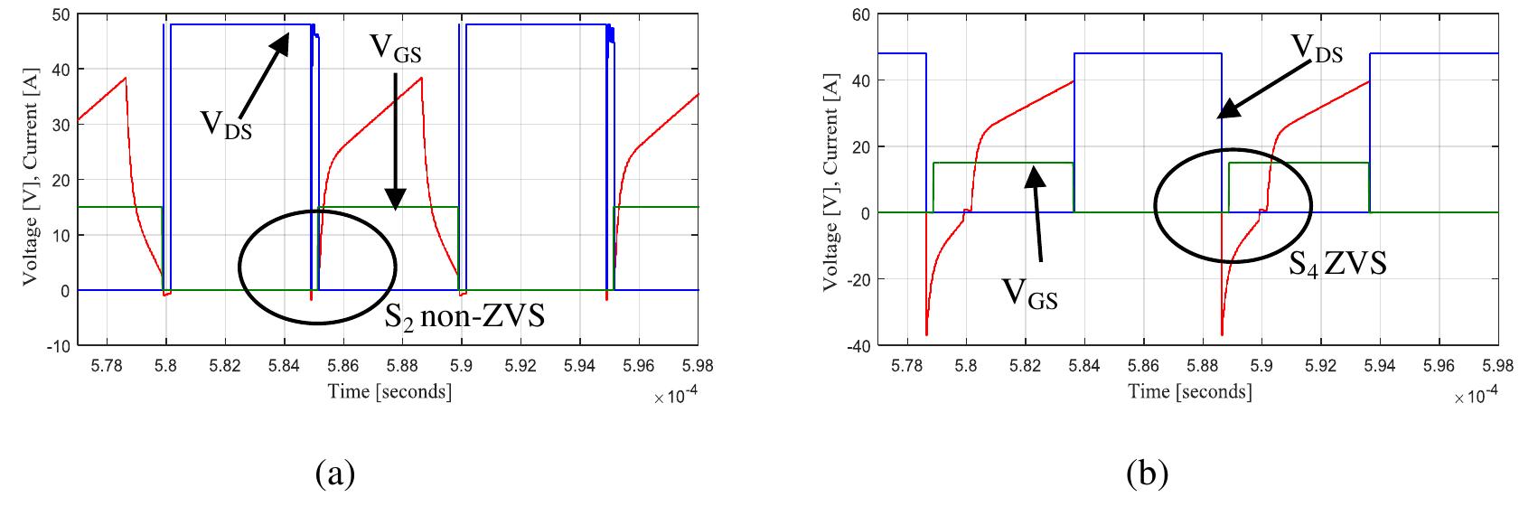
Let's first examine the lagging leg, which is the leg that terminates the power transfer and initiates the "freewheeling" or idling period. This transition occurs when the converter is delivering power and the primary current is at its peak.
This high current is the reason the lagging leg's ZVS is often described as "natural" or "easy" to achieve, especially at higher loads.
The process is as follows:
- The converter is in a power-transfer state (e.g., Q1 and Q4 are ON). The primary current, , is high, reflecting the full load current to the primary side.
- The lagging leg switch (Q4) is turned OFF.
- The large current flowing through the series inductance cannot stop instantly. It is redirected, flowing into the parasitic capacitances of the lagging leg. It charges the of the switch turning off (Q4) and discharges the of the switch about to turn on (Q3).
- Because the current is high, the inductor has a large amount of stored energy (). This energy is typically more than sufficient to fully discharge the capacitance of Q3, causing its to drop to zero and its body diode to conduct.
- During the dead-time, the controller turns ON Q3 while its body diode is already conducting. Since is effectively zero, there is no capacitive turn-on loss.
ZVS on the Leading Leg
Now, let's turn to the leading leg. This is the leg that terminates the freewheeling period and initiates power transfer. The situation here is quite different.
During the freewheeling period, the primary side of the transformer is effectively short-circuited, and the primary current is circulating. This circulating current is much lower than the peak current, corresponding to the valley of the primary current ripple.
The process follows the same pattern, but with one critical change:
- The converter is in a freewheeling state (e.g., Q2 and Q3 are ON). The primary current is at its minimum value for the cycle.
- The leading leg switch (Q2) is turned OFF.
- The smaller freewheeling current from is redirected to charge the of Q2 and discharge the of Q1.
- Because the current is low, the energy available for the transition () is significantly less.
- If this energy is insufficient to fully discharge the capacitance of Q1 before the dead-time ends, the switch will turn on with some voltage across it (partial ZVS or hard switching).
This is why the leading leg is the first to lose ZVS as the load decreases. At light loads, the freewheeling current can be so small that it provides almost no ZVS benefit, making the leading leg behave like a hard-switched converter.
To see this process animated, let's revisit the Toshiba video.
[ e - Learning ] Full Bridge Converter - Basics of Switching Power Supplies (5)
The video also illustrates the transition for the other leg, which corresponds to our leading leg discussion.
Watch the segment from 12:37 to 13:30. The process is identical in form: Q1 turns off, capacitances are charged/discharged by the inductor current, and the body diode of Q2 conducts, enabling ZVS for Q2. The key difference, not immediately obvious from the animation but critical in practice, is that the current driving this transition is much smaller than for the lagging leg.
Test your understanding!
You are reviewing the PCB of a PSFB converter that is failing efficiency targets at 20% load. The designer mentions that switching losses seem unexpectedly high. Based on today's lesson, which of the following is the most likely culprit?
a) The lagging leg is hard-switching due to excessive load current.
b) The leading leg has lost ZVS because the freewheeling current is too low at light load.
c) Both legs are hard-switching because the series inductance is too large.
Show answer
The correct answer is b) The leading leg has lost ZVS because the freewheeling current is too low at light load.
At light loads (like 20%), the peak current is still sufficient to provide ZVS for the lagging leg. However, the freewheeling current becomes very small, starving the leading leg of the energy it needs to achieve ZVS. This results in hard-switching and a sharp drop in efficiency at light load, which is a classic characteristic of PSFB converters.
A Deeper Look: The ZVS Condition
The condition for achieving complete ZVS can be stated simply: the inductive energy available must be greater than the capacitive energy that needs to be overcome.
ZVS Condition:
Where is the energy stored in the parasitic capacitances of the two MOSFETs in the leg.
Let's look at a more formal presentation of this from an application note by ROHM. This will add an important detail to our understanding.
Reduction in Switching Loss of Phase-Shift Full-Bridge ...
This document, 'Reduction in Switching Loss of Phase-Shift Full-Bridge,' provides the key equations that govern ZVS in each leg. We will not derive them, but examining their form is very instructive.
Please read Section 2-4, 'Conditions for accomplishing ZVS and importance of turn ON timing.' Focus on understanding the difference between Equation (1) for the lagging leg and Equation (2) for the leading leg. Note the extra term in the leading leg equation.
As you saw, the equations are:
- Lagging Leg:
- Leading Leg:
Notice the term in the leading leg equation. This represents the output filter inductor (), reflected to the primary by the square of the transformer turns ratio (). This tells us that the energy stored in the main output inductor also helps the leading leg achieve ZVS.
This creates an interesting trade-off:
- The lagging leg has a high current () but only the series inductance () to help it.
- The leading leg has a lower current () but gets help from both the series inductance () and the much larger reflected output inductance ().
In most practical designs, the lack of current in the leading leg is the dominant factor, making it the "harder" leg to achieve ZVS on, especially under light load conditions.
Conclusion
We've now uncovered the distinct ZVS behaviors of the two legs in a Phase-Shifted Full-Bridge converter. This asymmetry is a defining feature of the topology.
Key Takeaways:
- Lagging Leg ZVS: Achieved during the transition from power delivery to freewheeling. It benefits from the high peak primary current, making ZVS robust and "natural" at moderate to heavy loads.
- Leading Leg ZVS: Achieved during the transition from freewheeling back to power delivery. It suffers from low freewheeling current, making ZVS difficult to achieve, especially at light loads. This is often the primary source of inefficiency at low power.
- Energy Sources: The lagging leg transition is powered primarily by the energy in the series/leakage inductance (). The leading leg transition is powered by energy in both and the reflected output filter inductance ().
- Practical Impact: The leading leg's struggle for ZVS at light load is a critical performance characteristic to look for when reviewing a PSFB design. It dictates the converter's light-load efficiency curve.
In our next lesson, we will continue exploring the practical side of PSFB converters. We will examine the role that load current and series inductance play in defining the ZVS operational range and discuss the penalty of "circulating currents" that arises during the freewheeling phase.