Hello! Welcome back to our course on Finite State Machines.
In the last lesson, you learned how to create state diagrams, turning abstract ideas about behavior into a concrete visual plan. You practiced this by diagramming a door and a traffic light, and we looked at a simple diagram for an NPC's AI.
Today, we're going to master the reverse skill, which is just as important: reading and interpreting an existing state diagram. This is the final piece of the puzzle before we start coding. By the end of this lesson, you will be able to look at any state diagram and confidently identify the current state, all possible transitions, and the specific events that trigger them. This skill is essential for understanding, debugging, and collaborating on systems that use FSMs.
1. Reading the Blueprint: A Quick Review
A state diagram is the blueprint for an FSM. Before we start interpreting them, let's quickly review the main components.
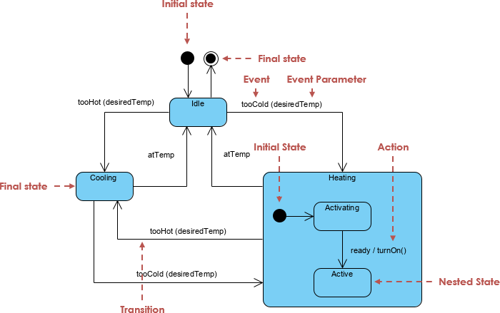
As a reminder:
- An FSM can only be in one state at any given time. This is its "current state."
- A transition (the arrow) is the only way to move from one state to another.
- An event (the label on the arrow) is the trigger that causes a transition to occur. If an event happens that doesn't have a corresponding transition from the current state, it's simply ignored.
With this in mind, let's practice reading a diagram.
2. Guided Interpretation: The Oven
We'll start with a common household appliance. The following video walks through the process of building a state diagram for an oven. As you watch, pay close attention to how new states are added and how events connect them.
Understanding State Machines, Part 1: What Are They?
The video 'Understanding State Machines, Part 1: What Are They?' by MATLAB provides an excellent, clear walkthrough of creating a state diagram for an oven. It perfectly illustrates how to read the diagram to understand the system's logic.
Please watch from 0:52 to 3:18. This segment will introduce the oven FSM and build it up from a simple two-state machine to a more complete three-state version.
Now that you've seen the diagram being built, let's analyze the final version shown in the video. Imagine the oven is powered on and its FSM is running. Let's test your interpretation skills with a few questions.
Question 1:
If the oven's current state is Idling (the heating element is temporarily off to maintain temperature), what are the possible states it can transition to, and what events cause those transitions?
Answer
From the `Idling` state, there are two possible transitions: 1. It can transition to the **`Heating`** state, triggered by the **`too cold`** event. 2. It can transition to the **`Off`** state, triggered by the **`off pressed`** event.Question 2:
The video narrator points out a logical flaw in the initial three-state diagram before adding the final transition. What would happen if the user pressed the "off" button while the oven was in the Idling state before that final transition was added?
Answer
Nothing would happen. The `off pressed` event would be ignored because there was no transition leading from the `Idling` state associated with that event. The oven would remain in the `Idling` state, which is clearly not the desired behavior. This is a great example of how drawing a diagram helps you find bugs in your logic before you've written any code.3. Application: A Game Character's Actions
Let's move from ovens to a more familiar context: game characters. The diagram below models the basic actions of a player character. Since you're experienced with Luau, you can imagine how you might try to code this with a series of if/elseif statements, and how quickly that could become complicated. The FSM provides a much cleaner map of the logic.
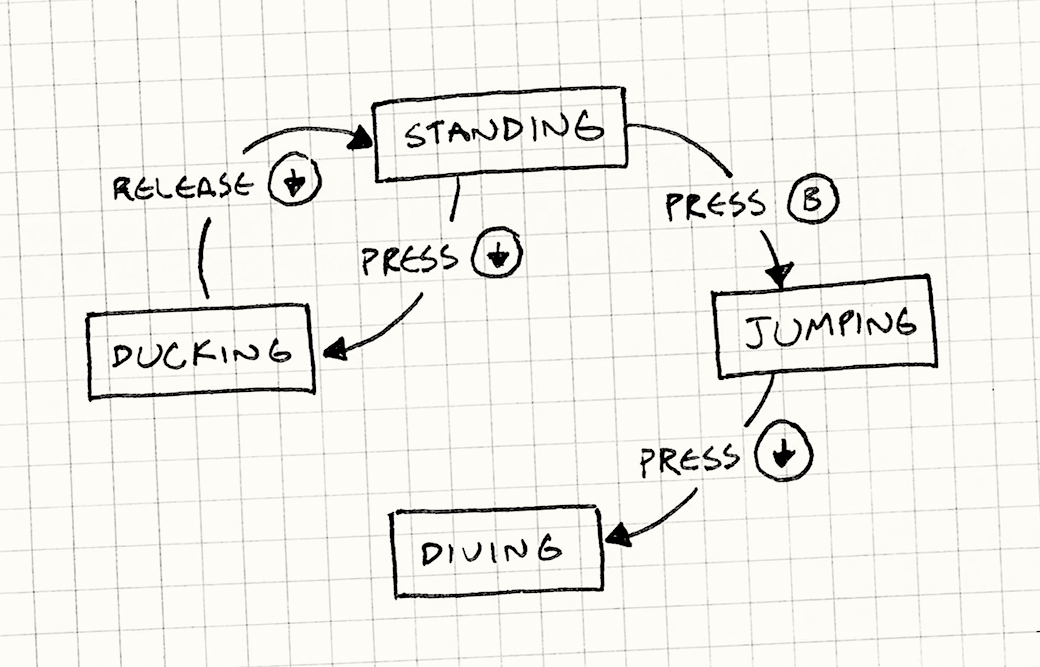
Let's analyze this character's behavior based only on the diagram.
Question 1:
The character is currently STANDING. What are the possible next states, and what specific user inputs (events) trigger the transitions to them?
Answer
From the `STANDING` state, there are two possible transitions: 1. Transition to **`JUMPING`**, triggered by the **`press B`** event. 2. Transition to **`DUCKING`**, triggered by the **`press down`** event.Question 2:
Suppose the player is in the JUMPING state and presses the 'B' button again. What happens?
Answer
According to this diagram, nothing. There is no outgoing transition from the `JUMPING` state for a `press B` event. To implement a double-jump, you would need to add another state (e.g., `DOUBLE_JUMPING`) or a transition from `JUMPING` back to itself with a condition, but this FSM doesn't support it. The diagram defines the character's abilities.Question 3:
Can the character go directly from JUMPING to STANDING?
Answer
No. The diagram shows no direct transition from `JUMPING` to `STANDING`. A real game would need a transition for when the character lands on the ground, likely from `JUMPING` (or a `FALLING` state) to `STANDING`. This diagram is incomplete, but it demonstrates how FSMs enforce strict rules about behavior.4. Adding Conditions to Transitions
Sometimes, an event alone isn't enough to decide if a transition should happen. You might need to check an additional condition. For example, a reload event should only transition the player to the Reloading state if they have reserve ammo. This extra check is called a Guard Condition.
The following resource provides a formal definition.
State Machine Diagram Tutorial
The article 'State Machine Diagram Tutorial' from Visual Paradigm offers a clear, technical breakdown of transitions. We'll focus on the section that defines the five parts of a transition, including the guard condition.
Please read the section titled 'Transition'. Focus on the list of five parts that make up a transition, especially the definitions for 'Event trigger' and 'Guard condition'.
The standard notation for a transition with a guard is: event [guard].
The transition only fires if the event occurs AND the guard condition is true.
Let's revisit the NPC AI diagram from our last lesson. Imagine we modify the transition from CHASE to ATTACK. It's now labeled: TARGET IN ATTACK RADIUS [has_line_of_sight].
Question: The TARGET IN ATTACK RADIUS event occurs (the player is close enough). Under what circumstance will the NPC not transition to the ATTACK state?
Answer
The NPC will not transition to the `ATTACK` state if the guard condition `[has_line_of_sight]` is false. For example, if the player is within range but hiding behind a wall, the guard fails, and the NPC remains in the `CHASE` state. Both the event must happen and the guard must be true for the transition to occur.Guard conditions are a powerful tool for adding nuanced logic to your FSMs without creating lots of extra states.
Conclusion
In this lesson, you've sharpened your ability to interpret state diagrams—a critical skill for any developer using FSMs. You learned to trace the logic of a system by identifying its current state, the transitions available from that state, and the events and guard conditions that control them.
Key Takeaways:
- To interpret an FSM diagram, you start at the current state and examine all outgoing arrows (transitions).
- Each transition is triggered by a specific event. If an event occurs that has no corresponding transition, it is ignored.
- A guard condition is an additional boolean check (
[is_true]) that must pass for a transition to fire. The transition occurs only ifeventhappens AND[guard]is true. - Reading diagrams allows you to understand system behavior, predict outcomes, and spot logical errors before implementation.
You have now completed the foundational theory of Finite State Machines! You know what they are, how to draw them, and how to read them. You're ready to start building.
In our next lesson, we will begin Module 2 and jump into the Roblox editor. You'll write your first FSM in Luau, starting with a straightforward implementation using simple if-elseif logic.