Welcome back! In our last lesson, we successfully translated the mathematical concept of a ray into a practical C++ ray class. We now have a fundamental tool for our ray tracer, but a ray is invisible on its own. To see anything, we need to cast these rays and record what they "see" on a digital canvas—an image file.
This brings us to our current goal: Describe the structure of the PPM image format for simple image writing.
Before we can write code to generate an image, we first need to understand the file format we'll be creating. In this lesson, we'll explore why a simple, text-based format like PPM is the perfect starting point for our project, and we'll break down its structure piece by piece. This knowledge will be the blueprint you use in the next lesson to write your very first image-generating program.
Why Not JPEG or PNG? The Case for a Simple Format
In your work as a VFX pipeline TD, you're familiar with sophisticated image formats like OpenEXR, which handle multiple layers, arbitrary data channels, and various compression schemes. For learning, however, starting with such complexity would distract from our main goal: understanding the ray tracing algorithm itself.
We will use the Portable Pixmap (PPM) format. Its key advantage is its simplicity. It's a plain text file, which means we can write it without any special libraries and even inspect or edit it with a simple text editor. This lets us focus entirely on rendering logic.
The following video from Jacob Sorber gives an excellent overview of why PPM is an ideal choice for programmers who want to build everything from the ground up.
PPM might be the best DIY image format (at least for beginners).
This video, 'PPM might be the best DIY image format', makes a compelling case for using PPM when you're learning about image processing. It highlights the trade-off between simplicity and file size.
Watch from the beginning to 6:50. The first part (until 2:09) explains the 'why'. The second part (from 3:43 to 6:50) provides a detailed breakdown of the P3 PPM format, which is the specific type we'll be using. Pay close attention to the explanation of the header and the pixel data.
As the video explains, while PPM files are much larger than compressed formats like JPEG, their "dirt simple" structure is a huge advantage for us.
The Anatomy of a P3 PPM File
The PPM format has a few variants. We will focus on the P3 type, which represents a full-color image using plain ASCII text. Every P3 PPM file is composed of two main parts: the header and the body.
Let's look at a classic example that shows the text data and the image it produces side-by-side.
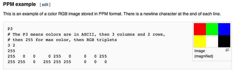
Let's break down what you're seeing in the text portion.
1. The Header
The header provides the metadata that an image viewer needs to interpret the pixel data correctly. It consists of three key pieces of information, usually on the first few lines.
For a more formal breakdown, please read the following resource from a computer science course at Swarthmore College.
CS35: Lab 1 - PPM Image Format
This lab document, 'CS35: Lab 1 - PPM Image Format', provides a concise and clear definition of the PPM header components.
Read the section titled 'Image Header'. It clearly defines the 'magic number', image dimensions, and maximum color value.
To summarize, the header contains:
- Magic Number:
P3. This string identifies the file as a color ASCII PPM file. - Dimensions: Two integers for the image width and height in pixels, separated by a space.
- Maximum Color Value: An integer representing the maximum value for each color component. This is typically
255, which corresponds to the standard 8-bit range for RGB colors (0-255).
So, a header for a 800x600 image would look like this:
P3
800 600
255
2. The Body (Pixel Data)
Immediately following the header is the body, which contains the color data for every pixel in the image.
The pixels are listed in scanline order:
- Rows are written from top to bottom.
- Within each row, pixels are written from left to right.
Each pixel is represented by a triplet of integers: its Red, Green, and Blue values, separated by spaces.
For a deeper look at the body and how it relates to the header, please review the next section of the same resource.
CS35: Lab 1 - PPM Image Format
This section of the lab document explains the structure of the PPM image body.
Read the section titled 'Image Body'. Note the explanation of RGB triplets and the important point that whitespace (spaces, tabs, newlines) is flexible after the header. This means you don't have to put each pixel or each row on a new line, though it often helps with readability.
For example, the first few pixels of a file might look like this:
255 0 0     // First pixel (top-left), pure red
0 255 0     // Second pixel, pure green
0 0 255     // Third pixel, pure blue
...
Test your understanding!
Imagine you want to create a tiny 2x2 pixel image. The top-left pixel should be white, the top-right red, the bottom-left green, and the bottom-right blue.
What would the complete text content of the P3 PPM file for this image look like?
Show answer
The file content would be:
P3
2 2
255
255 255 255  # Top-left (white)
255 0 0      # Top-right (red)
0 255 0      # Bottom-left (green)
0 0 255      # Bottom-right (blue)
(Note: Comments with # are not part of the PPM standard but are added here for clarity. The whitespace is also flexible; all the pixel values could be on a single line).
From Structure to C++ Code: A Preview
Now that you understand the structure, you can see how straightforward it would be to generate this format using C++. The Ray Tracing in One Weekend book, which is our primary guide, demonstrates this by simply writing the required text to the standard output stream (std::cout).
Ray Tracing in One Weekend Series
This is the first chapter of our main textbook, 'Ray Tracing in One Weekend'. It introduces the PPM format and immediately provides the C++ code to generate a simple gradient image. This bridges the gap between understanding the format and preparing to write it.
Read the section 'Output an Image', focusing on the C++ code block. You don't need to implement this now, but observe how the code first prints the header (P3, width, height, 255) and then uses nested loops to iterate through each pixel (j for height, i for width) and print its RGB values.
The approach shown in the book is elegant in its simplicity. By printing text that conforms to the P3 PPM specification, we can create an image file without any external dependencies.
Conclusion
In this lesson, we've focused on understanding the "what" and "why" of the PPM image format. This foundational knowledge is crucial before jumping into code.
Key Takeaways:
- The PPM (P3) format is a simple, text-based image format ideal for learning computer graphics from scratch.
- Its structure is divided into a header and a body.
- The header specifies the format (
P3), image dimensions (width, height), and the maximum color value (usually 255). - The body contains RGB integer triplets for each pixel, ordered from top-to-bottom and left-to-right.
- Because it's plain text, we can generate PPM files using basic C++ file I/O or even just by printing to the console and redirecting the output.
Next Steps
You are now fully prepared for the next, exciting step. In the upcoming lesson, you will take on the learning outcome: Write a program that outputs a gradient image in PPM format by mapping pixel coordinates to colors. We will implement the code we previewed today, combining our knowledge of the PPM format with C++ file streams to create the very first visual output from our own renderer.