Hello! Welcome back to our course on building a ray tracer.
In our last lesson, we put the finishing touches on our material system for opaque objects by implementing gamma correction. This crucial step ensures that our physically-based lighting calculations are displayed with perceptual accuracy, a fundamental concept in the linear workflow used in professional renderers like Arnold and Karma.
Now, we're ready to venture beyond opaque surfaces and into the fascinating world of transparent materials. This lesson will lay the groundwork for rendering things like glass, water, and diamonds. To do that, we need to understand how light behaves when it passes from one medium to another.
Our goal for today is to explain Snell's law and the role of refractive indices in light refraction. We will explore the physical principle that causes light to bend and derive the simple but powerful law that governs this behavior.
1. The Principle of Least Time
When you look at an object underwater, it often appears distorted or in a different position than it actually is. This phenomenon is called refraction. It happens because light travels at different speeds in different media. For instance, light moves slower in water than it does in air. This change in speed causes the light's path to bend at the interface between the two media.

But why does it bend? The underlying principle is one of the most elegant in physics: Fermat's Principle of Least Time. It states that out of all possible paths light might take to get from one point to another, it takes the path that requires the least amount of time.
A straight line is the shortest distance, but if part of that path is through a "slower" medium, it might not be the fastest route. Light performs an optimization: it travels a bit further in the "fast" medium to shorten its path through the "slow" medium, minimizing the total travel time.
The following video provides a brilliant and intuitive explanation of this idea.
Snell's law proof using springs
This video from 3Blue1Brown explains Fermat's Principle and uses a clever mechanical analogy to show why it leads to light bending, without requiring any calculus.
Please watch the first 1 minute and 45 seconds. Focus on how the goal of minimizing travel time forces the light ray to take a 'kinked' path instead of a straight one.
2. Refractive Index and Snell's Law
To describe refraction mathematically, we first need to quantify how "slow" a medium is for light. We do this using the index of refraction (IOR), often denoted by the Greek letter eta () or .
The index of refraction of a medium is the ratio of the speed of light in a vacuum () to the speed of light in that medium ():
- A vacuum has an IOR of exactly 1.
- Air has an IOR very close to 1 (≈1.0003), so in graphics, we almost always treat it as 1.
- Water has an IOR of about 1.33.
- Glass has an IOR ranging from 1.5 to 1.7.
A higher IOR means light travels slower in that medium. This property is what causes light to bend more or less sharply.
The relationship between the angles and the indices of refraction is described by Snell's Law. If a ray of light passes from a medium with IOR to a medium with IOR , the law states:
Where:
- is the angle of incidence.
- is the angle of refraction.
- Crucially, both angles are measured between the ray and the surface normal.
The following reading provides a concise summary of these definitions.
Introduction to Shading (Reflection, Refraction and Fresnel)
The 'Refraction' section of this article from Scratchapixel defines the index of refraction and Snell's Law, providing a solid foundation for our work.
Read from the start of the 'Refraction' section down to the statement of Snell's Law. Focus on the definition of the index of refraction (η) and the formula for the law.
With your background in CS and mathematics, you might be interested to see how Fermat's Principle leads directly to Snell's law using calculus. The next video does exactly that.
This video from Zach Wissner-Gross provides a formal derivation of Snell's Law from Fermat's Principle, setting up the geometry and using calculus to find the path of minimum time.
Watch from 00:37 to the end. You don't need to memorize the derivation, but follow along with the logic of setting up the time equation and minimizing it to see how Snell's law emerges.
Test your understanding!
A ray of light travels from water () into an unknown transparent material. The angle of incidence () is 45°. The angle of refraction () is measured to be 32°.
- Is the unknown material optically denser (higher IOR) or less dense (lower IOR) than water?
- Calculate the index of refraction of the unknown material.
Show answer
- Since the light ray bends towards the normal (), the new material must be optically denser than water, meaning it has a higher IOR.
- Using Snell's Law:
The unknown material has an IOR of approximately 1.77.
3. A Key Consequence: Total Internal Reflection
Snell's Law has a fascinating consequence. Let's rearrange the formula to solve for the angle of refraction:
Consider a ray going from a denser medium to a less dense one, like from water () to air (). In this case, . As the angle of incidence increases, the value of also increases. It is possible for the entire right-hand side of the equation to become greater than 1.
But the sine of an angle can never be greater than 1!
When this happens, there is no real solution for . Physically, this means no refraction occurs. The light cannot escape the denser medium. Instead, 100% of the light is reflected back from the surface, a phenomenon called Total Internal Reflection (TIR). The surface acts like a perfect mirror.
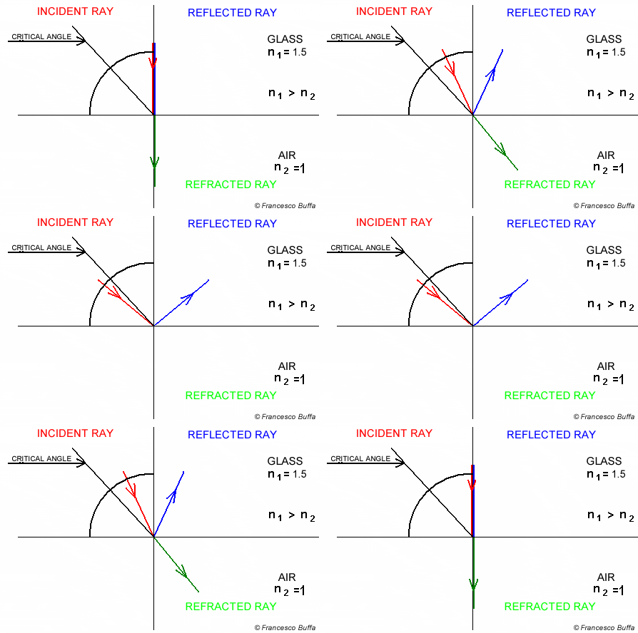
This is why, if you are underwater and look up at the surface at a steep angle, you see a reflection of the bottom of the pool instead of the world above. Total internal reflection is also the principle behind fiber optics. This is a critical effect that we will need to handle when we implement our dielectric material.
The Ray Tracing in One Weekend guide also provides a good, practical summary of this effect.
This section from Peter Shirley's book introduces dielectrics and quickly covers both Snell's Law and the practical issue of total internal reflection.
Read the paragraph in Chapter 9 starting 'The refraction is described by Snell’s law...' and the following paragraph that explains 'total internal reflection'. This reinforces the concepts in a practical context.
Conclusion
In this lesson, we've unpacked the physics behind one of the most visually rich effects in computer graphics. You now have the conceptual tools to understand how transparent objects bend light.
Key Takeaways:
- Refraction is the bending of light as it passes between media with different speeds.
- The Index of Refraction (IOR) () of a material quantifies how much it slows down light (). A higher means a slower speed.
- Snell's Law, , is the formula that governs the change in a light ray's direction.
- Total Internal Reflection (TIR) is a critical side-effect of Snell's Law that occurs when light tries to move from a denser to a less-dense medium at a sufficiently high angle of incidence. In this case, all light is reflected.
Next Steps
We now understand the what and why of refraction. Our next task is to translate this into code. In the next lesson, we will focus on the geometry of the problem and derive the 3D vector formula for the refracted ray. Your strong foundation in linear algebra will be very helpful as we use vector decomposition to construct the new ray direction based on Snell's Law.