In our last lesson, we built a high-level model of a microcontroller, understanding it as a system with a core, peripherals, and a memory map that connects them. We established that controlling hardware is achieved through memory-mapped I/O—writing to specific memory addresses. Now, we confront the essential next question: how do we find those addresses and understand what data to write?
This lesson is your introduction to the primary skill of a bare-metal embedded engineer: navigating technical documentation. For the companies you aspire to work for, like SpaceX or Shield AI, the ability to read and precisely interpret hardware documentation isn't just a skill; it's a fundamental requirement for building reliable and safe systems. We will focus on the two "sources of truth": the datasheet and the reference manual. By the end of our session, you'll be able to dissect these documents to find register addresses, decode bit-field definitions, and identify key electrical characteristics.
The Two Bibles: Datasheet vs. Reference Manual
Before you can control a peripheral, you need to consult its documentation. This information is typically split into two key documents provided by the chip manufacturer. Confusing them is a common beginner mistake.
-
The Datasheet: This document is concerned with the chip as a physical and electrical component. It answers questions like:
- What is the pinout? Which physical pin corresponds to which function?
- What are the voltage and current limits? (e.g., "Absolute Maximum Ratings")
- How fast can it run at a given voltage?
- What are its power consumption characteristics?
- What physical packages is it available in?
-
The Reference Manual: This document is concerned with the chip as a programmable device. It's your guide to the software interface. It answers questions like:
- What is the detailed memory map?
- How do I configure a specific peripheral (like a UART or GPIO)?
- What are the addresses of all the control registers?
- What does each bit within a register do?
In short: use the datasheet to design your circuit board and the reference manual to write your firmware.
The following video provides an excellent overview of this distinction and demonstrates how to find these documents for a specific microcontroller.
Datasheet and Reference Manual Overview: STM32 Bare Metal Software from scratch #2
This video from AsabreTech introduces the central role of datasheets and reference manuals in bare-metal programming.
Watch the first five minutes. Pay close attention as the presenter first finds and downloads both the datasheet and reference manual, emphasizing that you need both. Then, focus on the walkthrough of the block diagram in the datasheet, which visualizes the peripherals and the buses that connect them.
As you saw, the block diagram gives you a bird's-eye view of the chip's architecture, showing all the available hardware modules and how they are interconnected.

The datasheet also contains pinout diagrams, which are crucial for connecting the microcontroller to other components in a circuit.
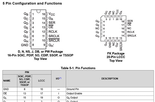
From Memory Map to Register Bits: A Practical Walkthrough
Let's put this into practice. Imagine our goal is to turn on a single LED connected to a GPIO pin. Based on the previous lesson, we know this involves writing to a memory-mapped register. But which one? The process involves a systematic treasure hunt through the reference manual.
Step 1: Find the Peripheral's Base Address
First, we need to know where the peripheral "lives" in the 4GB memory space. This starts with the memory map.
Datasheet and Reference Manual Overview: STM32 Bare Metal Software from scratch #2
This segment of the AsabreTech video explains how to navigate to the memory map section of the reference manual.
Watch from this section on the memory map. The key concept here is that large blocks of memory are reserved for different functions (Flash, RAM, Peripherals). The presenter shows how peripherals are located within specific bus regions (like APB and AHB), each with its own starting address.
The memory map gives you the starting address of the bus that the peripheral is on (e.g., IOPORT or AHB1). The next step is to find a table, often called "Peripheral register boundary addresses" or similar, which lists the offset of each peripheral from that bus's starting address.
For example, if the IOPORT bus starts at 0x40020000 and the documentation says GPIOA is at an offset of 0x0000, its base address is 0x40020000. If GPIOB is at offset 0x0400, its base address is 0x40020400.
Step 2: Don't Forget the Clock!
A crucial and often-missed step for beginners is enabling the peripheral's clock. To save power, most peripherals are turned off by default. You must explicitly turn them on before you can use them. This is done via the RCC (Reset and Clock Control) peripheral.
You'll need to repeat the process:
- Find the base address of the RCC peripheral in the memory map.
- Go to the RCC chapter in the reference manual.
- Find the correct clock enable register for the bus your target peripheral is on (e.g.,
AHB1ENRfor a peripheral on the AHB1 bus). - Find the specific bit within that register that corresponds to your peripheral (e.g.,
GPIOAENfor GPIO Port A).
The following guide walks through this exact process. While it includes C code snippets (which we will cover in detail later), focus on how the author finds the necessary information in the documentation.
The Ultimate Guide to STM32 - Sine Lab
This guide from Sine Lab is an excellent, practical walkthrough of programming a microcontroller from scratch. We will focus on the sections where the author consults the documentation to find addresses and bit definitions.
Please read the section titled "Creating Blink (main.c)". First, focus on the part where the author finds the peripheral locations. Start reading from this paragraph. Notice how they first define the base addresses of the main peripheral buses (AHB, APB1, etc.) from the memory map. Next, see how they find and configure the RCC. Read from this section. Pay attention to the process: Find the RCC peripheral's base address in the "peripheral register boundary addresses" table. Go to the RCC chapter to find the register's offset (e.g., the GPIO clock enable register is at offset 0x2C). Look at the register's description to find the name of the bit that enables the specific peripheral (e.g., GPIOA).
Step 3: Decode the Peripheral's Registers and Bit-Fields
Now that the peripheral has power, you can configure it. This is the final and most detailed step.
- Navigate to the chapter for your peripheral (e.g., "GPIO").
- Find its register map. This will list all the control registers with their offsets from the peripheral's base address.
- Click on a specific register, for example, the Mode Register (
MODER), which controls whether a pin is an input, output, or something else. - Examine the bit-field diagram for that register. This is the most important part. It shows you what each bit or group of bits controls.
This video segment provides a crystal-clear explanation of a GPIO Mode Register.
Datasheet and Reference Manual Overview: STM32 Bare Metal Software from scratch #2
Let's return to the AsabreTech video, which now dives into the GPIO register details.
Watch the segment from "I want you to set the GPI register". The presenter explains: The x in GPIOx_MODER is a placeholder for the port (A, B, C...). The register is 32 bits wide. For this specific MCU, each pin's mode is controlled by a 2-bit field. For example, MODER0 (bits 1:0) controls pin 0, MODER1 (bits 3:2) controls pin 1, and so on. The meaning of the values (e.g., 00 for Input, 01 for Output).
Let's consolidate this with the text guide.
The Ultimate Guide to STM32 - Sine Lab
We will now revisit the Sine Lab guide to see the same process in text.
Continue reading "Creating Blink (main.c)" from the heading "Now we can finally get around". Here, the author finds the GPIOA base address from the boundary table and then defines the offsets for the key registers (MODER, ODR). The guide then states what the reference manual says: to set a pin to output, the corresponding 2-bit pair in MODER must be set to 01.
This is the core loop of bare-metal development: look up the memory map for the base address, look up the peripheral chapter for the register offset and bit-field definitions, and then (as we'll see in the next lesson) write the code to make it happen.
A Note on Electrical Characteristics
Finally, let's briefly return to the datasheet. Suppose we have successfully configured our GPIO pin as an output. How much current can it safely provide to light up our LED? If we draw too much, we could permanently damage the microcontroller.
The answer is in the datasheet's "Electrical Characteristics" section. You would look for tables specifying "DC characteristics" or "I/O port characteristics". There, you will find values like:
- : Maximum output current a pin can source when driving high.
- : Maximum output current a pin can sink when driving low.
- : Minimum guaranteed output voltage when the pin is high.
- : Maximum input voltage that will be interpreted as low.
Knowing these values is critical for interfacing with other electronic components and is a key part of the hardware design process that accompanies firmware development.
Conclusion
In this lesson, we've demystified the documentation that underpins all low-level embedded programming. You now have a systematic process for finding the information needed to control hardware.
Let's review the key takeaways:
- The Reference Manual is your guide to programming the chip. Use it to find the memory map, peripheral base addresses, register offsets, and bit-field definitions.
- The Datasheet is your guide to the chip's physical and electrical properties. Use it to find pinouts, voltage levels, and current limits.
- The workflow for enabling a peripheral is typically:
- Use the RCC registers to enable the peripheral's clock.
- Use the peripheral's control registers (like
MODERfor GPIO) to configure its function. - Use the peripheral's data registers (like
ODRfor GPIO) to interact with it.
You now understand what information you need and where to find it. In our next lesson, we will focus on the how: using bitwise operations in C/C++ to precisely manipulate the individual register bits you've just learned to identify.