Introduction
Welcome back! In our last lesson, you learned how to combine the individual model, view, and projection matrices into a single, efficient Model-View-Projection (MVP) matrix on the CPU. We established that the correct order of multiplication is MVP = Projection * View * Model and created the necessary C functions to build this matrix.
This lesson is the exciting conclusion to our 3D transformation journey. We will achieve the following learning outcome: Apply the MVP transformation to vertex coordinates in the vertex shader.
You will learn how to:
- Pass the MVP matrix from your C application to the GPU.
- Write the GLSL vertex shader code to use this matrix.
- Transform a vertex's coordinates from its local model space all the way to clip space in a single operation.
By the end of this lesson, the flat triangle we've been rendering will finally be positioned and projected in a proper 3D world, responding to the camera and model transformations you define.
The Vertex Shader's Purpose
Let's start where the action happens: the vertex shader. As you know, its primary responsibility is to compute the final, transformed position of each vertex and assign it to the special output variable gl_Position. The coordinates assigned to gl_Position must be in clip space.
In the previous lesson, we saw that we can pre-calculate the MVP matrix on the CPU. This matrix encapsulates the entire transformation from an object's local coordinates to the final clip space coordinates. This simplifies the vertex shader tremendously.
The following tutorial section provides a clear explanation and the exact GLSL code for this process.
Entering Third Dimension - OpenGL 4 - Tutorials
Let's examine how the vertex shader uses the MVP matrix. This tutorial provides an excellent breakdown.
Please read the section titled 'Vertex shader'. Focus on these key points: How the modelMatrix, viewMatrix, and projectionMatrix are received as uniform variables. How they are combined into a single mvpMatrix. The final multiplication: mvpMatrix * vec4(vertexPosition, 1.0). The explanation for converting the vec3 vertex position into a vec4 by adding a 1.0 as the w component.
As the resource explains, the vertex shader becomes very concise:
#version 330 core
layout (location = 0) in vec3 aPos; // Vertex position from VBO

// We can receive the combined MVP matrix directly
uniform mat4 mvp;

void main()
{
    // Transform the vertex position to clip space
    // We convert aPos to a vec4 for matrix multiplication
    gl_Position = mvp * vec4(aPos, 1.0);
}
This simple line of code, gl_Position = mvp * vec4(aPos, 1.0);, is the culmination of all the 3D math we've studied. It takes a vertex in its original local space and, in one operation on the GPU, projects it into the final coordinate system ready for clipping and rasterization.
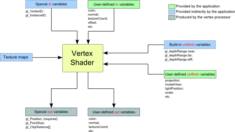
The diagram below visualizes the data flow for the vertex shader, which should help solidify this concept.
Sending the MVP Matrix to the Shader
How do we get the mvp matrix, which we calculate in our C code, over to the mvp uniform in our GLSL shader? This is done through a few OpenGL functions.
A uniform is a global variable in a shader program that can be set by the CPU application. Its value is "uniform" across all vertices and fragments processed in a single draw call.
The process has two steps:
1. Get the Uniform's "Location"
First, after you've compiled and linked your shader program, you need to ask OpenGL for the location (think of it as an ID or handle) of the uniform variable. You only need to do this once after creating the shader program.
// shader_program is the ID you got from glCreateProgram and glLinkProgram
GLuint mvp_location = glGetUniformLocation(shader_program, "mvp");
Here, "mvp" must exactly match the name of the uniform variable declared in your vertex shader.
2. Send the Matrix Data
Now, inside your main render loop (before you make a draw call like glDrawElements), you can send the matrix data to this location.
// mvp_matrix is your 4x4 float array calculated on the CPU
glUniformMatrix4fv(mvp_location, 1, GL_FALSE, &mvp_matrix[0][0]);
Let's break down the arguments for glUniformMatrix4fv:
mvp_location: The ID we just retrieved.1: The number of matrices we are sending. We are just sending one.GL_FALSE: This tells OpenGL whether to transpose the matrix. Since you've designed your math library to use column-major order (as is standard for OpenGL), you should set this toGL_FALSE.&mvp_matrix[0][0]: A pointer to the first element of your matrix data. This is how OpenGL accesses the 16 floats that make up your matrix.
This video clip provides a nice visual of this workflow in a C++ context, which is conceptually identical to what we're doing in C.
Model View Projection Matrices in OpenGL
The following video from The Cherno shows this process using C++ and the GLM library. Focus on the concept of creating a matrix and passing it to a shader uniform before drawing.
Watch from 07:12 to 08:16. The code demonstrates passing a matrix (called MVP in the C++ code) to a uniform of the same name in the shader. This is precisely the C-to-GLSL bridge we are building.
Practical Implementation
Let's integrate this into the main loop of your C application. The following code snippet shows the complete process for a single frame.
// --- In your application setup (after creating shader program) ---

// Get the location of the "mvp" uniform from the vertex shader
GLuint mvp_location = glGetUniformLocation(shader_program, "mvp");


// --- In your main render loop ---

// 1. Clear the screen
glClear(GL_COLOR_BUFFER_BIT | GL_DEPTH_BUFFER_BIT); // Note: also clearing the depth buffer now

// 2. Calculate the individual matrices on the CPU
// Model Matrix (positions the object in the world)
mat4 model_matrix;
// For now, let's just place the triangle at the origin without rotation or scale
mat4_identity(model_matrix);

// View Matrix (positions the camera)
mat4 view_matrix;
vec3 camera_pos   = {0.0f, 0.0f, 3.0f}; // Place camera 3 units back along Z-axis
vec3 camera_target = {0.0f, 0.0f, 0.0f}; // Look at the world origin
vec3 up_vector    = {0.0f, 1.0f, 0.0f};  // 'Up' is the positive Y direction
mat4_look_at(view_matrix, camera_pos, camera_target, up_vector);

// Projection Matrix (defines the camera's lens)
mat4 projection_matrix;
float fov = 45.0f * (3.14159f / 180.0f); // 45-degree field of view, in radians
float aspect_ratio = 800.0f / 600.0f;    // Assuming an 800x600 window
float near_plane = 0.1f;
float far_plane = 100.0f;
mat4_perspective(projection_matrix, fov, aspect_ratio, near_plane, far_plane);

// 3. Combine into the final MVP matrix
mat4 mvp_matrix;
mat4 view_projection_matrix;
// Remember the order: P * V * M
mat4_mul(view_projection_matrix, projection_matrix, view_matrix);
mat4_mul(mvp_matrix, view_projection_matrix, model_matrix);

// 4. Use the shader program and send the MVP matrix to the uniform
glUseProgram(shader_program);
glUniformMatrix4fv(mvp_location, 1, GL_FALSE, &mvp_matrix[0][0]);

// 5. Bind the VAO and draw the object
glBindVertexArray(your_vao_id);
glDrawArrays(GL_TRIANGLES, 0, 3); // Or glDrawElements if you are using an EBO

// 6. Swap buffers to display the rendered frame
glfwSwapBuffers(window);
When you run this code with your simple triangle, it might not look dramatically different at first, but it is now being rendered through a full 3D perspective projection. Try changing the camera_pos vector—for example, to {0.5f, 0.5f, 3.0f}—and you will see the triangle shift on the screen as if you've moved the camera. You have successfully rendered your first 3D scene!
Conclusion
Congratulations! You have now connected the world of 3D mathematics on the CPU with the rendering power of the GPU. This is a milestone in building a game engine.
Key Takeaways:
- The vertex shader's primary job is to calculate
gl_Positionin clip space. - The MVP matrix, pre-calculated on the CPU, transforms vertices from local space to clip space in a single shader operation:
gl_Position = mvp * vec4(aPos, 1.0);. - Uniforms are the bridge for sending data from the C application to GLSL shaders.
- The functions
glGetUniformLocationandglUniformMatrix4fvare used to find and update matrix uniforms. - The full rendering loop involves calculating matrices, combining them, sending the result to the shader, and then issuing a draw call.
Preview of the Next Lesson:
We can now render a triangle in 3D space. The next logical step is to render something more complex. In the next lesson, we will render a 3D cube using indexed drawing. This will involve defining the 8 vertices and 12 triangles that make up a cube and introducing Element Buffer Objects (EBOs) as an efficient way to describe how those vertices connect to form faces.