Hello! Let's get started with the final lesson in our "3D Math Fundamentals" module.
Introduction
In our previous lessons, we've built a solid foundation. We started with vectors and basic matrix operations, combined transformations into a single model matrix (M), and then understood how homogeneous coordinates allow us to use 4x4 matrices to represent all these transformations uniformly.
So far, we have successfully placed an object in a "world" using its model matrix. But a 3D scene is incomplete without a viewer. We need a camera to define our point of view.
Today's learning outcome is to construct a view matrix to position and orient a camera in the world. The view matrix (V) is the second major transformation in the Model-View-Projection (MVP) pipeline. It takes all the objects from world space and transforms them into camera space (also called view space), which is the world as seen from the camera's perspective.
We will cover:
- The conceptual role of the view matrix.
- The three key parameters needed to define a camera's viewpoint: its position, a target point, and an "up" direction.
- The mathematical steps to derive a
lookAtmatrix from these parameters. - How to implement this logic in code.
By the end of this lesson, you'll be able to position a virtual camera anywhere in your 3D scene and have it look in any direction.
The Camera Transformation
A common misconception is that we move the camera object through the world. In reality, for rendering purposes, we do the exact opposite. We move and rotate the entire world so that the camera is at the origin (0,0,0) and looking down a specific axis (by convention, the negative Z-axis in OpenGL).
This means the view matrix is the inverse of the camera's own transformation in the world. Think of it this way: if you have a matrix that places a camera object at a certain position and orientation in the world (its model matrix), the view matrix is the transformation that undoes this for every other object, bringing the entire world into the camera's local coordinate system.
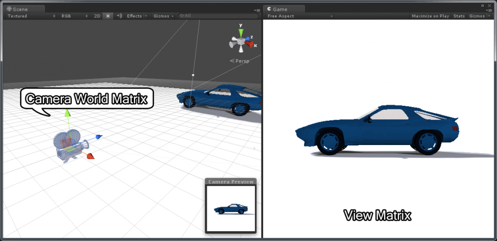
This process transforms vertices from world space to camera space.
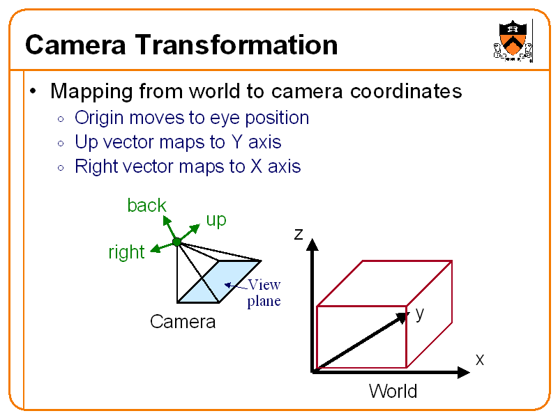
Defining a Camera with lookAt
To define the camera's orientation, we don't need to manually calculate rotation angles. A more intuitive method is to specify three things, just like a photographer would:
- Eye Position (
eye): Where is the camera located in world space? - Target Position (
targetorcenter): Where is the camera looking? - Up Vector (
up): Which direction is "up" from the camera's perspective? This helps orient the camera and prevent it from being tilted sideways. It's usually set to the world's "up" direction, like(0, 1, 0).
OpenGL [Episode 30] [Theory] The View Matrix
Let's watch a short segment from a video by Mike Shah that introduces these three parameters and builds the intuition for how they define a camera's view.
Watch from 04:15 to 07:40. The video explains the role of the eye, center (target), and up vectors in constructing the view matrix, using the example of the glm::lookAt function.
Deriving the View Matrix
Now for the core of the lesson: how do we get from eye, target, and up to a 4x4 view matrix? The process involves creating a new coordinate system (an orthonormal basis) for the camera and then constructing a matrix that performs a change of basis from the world system to this new camera system.
Deriving the View matrix - Swarthmore College CS
The following article provides a clear, step-by-step mathematical derivation of the view matrix. It's a great exercise in applying the vector operations we've learned.
Please read the section titled 'Deriving the View matrix'. Follow the steps carefully: How the basis vectors of the camera's frame (\hat{n}, \hat{r}, and \hat{u}) are calculated using the eye, at (target), and up inputs. This relies heavily on vector subtraction, normalization, and the cross product. How these basis vectors and the eye position are used to build a transformation matrix \mathbf{M^T} that converts from eye coordinates to world coordinates. Why the matrix we actually need is the inverse, \mathbf{M^{-T}}, which converts from world coordinates to eye coordinates. How the final view matrix is constructed using the properties of rotation and translation matrix inverses.
Let's summarize the key steps from the article for building our camera's coordinate system, using R, U, and D for the right, up, and direction axes:
-
Calculate the Direction axis (Z-axis): This axis should point from the target towards the camera.
D = normalize(eye - target) -
Calculate the Right axis (X-axis): This is perpendicular to the direction axis and the world's up vector. The cross product gives us this.
R = normalize(cross(world_up, D)) -
Calculate the Up axis (Y-axis): This must be perpendicular to both the Right and Direction axes. We can find it with another cross product. This gives us the camera's true
upvector, which is guaranteed to be orthogonal to the other two axes.U = cross(D, R)
The resulting lookAt view matrix that transforms world points into camera space is:
The top-left 3x3 part is the rotation, and the rightmost column is the translation. Notice how the translation part is -dot(axis, eye). This is the result of applying the inverse translation first (-eye), and then rotating that vector into the new coordinate system.
Implementing the lookAt Matrix
Since your goal is to build an engine from scratch, you won't be using a pre-made library function like glm::lookAt. You'll implement this logic yourself. This is a fantastic exercise.
You'll need to create a function, let's call it mat4_look_at, that takes eye, target, and world_up vectors and returns a mat4. Inside this function, you'll perform the exact steps we just derived.
OpenGL with C++ 5: Transformations
The following video demonstrates a complete from-scratch implementation of a 'look at' matrix in C++. The logic is directly transferable to C, and it will be a great guide for writing your own version.
Watch from 36:45 to 56:15. This is a longer segment, but it's pure gold for your goal. (36:45 - 48:51) The first part explains the theory behind the view transform. It frames it as the inverse of the camera's model transform, which reinforces what we've discussed. It also derives the matrix, which will serve as a good review of the article you just read. (48:51 - 56:15) The second part is the implementation. Pay close attention to how the code mirrors the math. The author implements the necessary helper functions (dot, normalize, cross) and then uses them to build the final createLookAtMatrix function. This is exactly what you will do in your own C math library.
As you build your mat4_look_at function, you will implement the following logic:
- Implement or use your existing vector functions for subtraction, normalization, cross product, and dot product.
- Inside
mat4_look_at, compute theD,R, andUaxis vectors as described above. - Construct the final 4x4 matrix, filling in the 16 float values according to the derived formula, including the dot products for the translation components.
Conclusion
Congratulations on completing the "3D Math Fundamentals" module! You've covered the essential mathematics for manipulating objects and a camera in a 3D environment.
Key Takeaways:
- The view matrix transforms vertices from world space to camera space, creating the illusion of a camera viewing the scene.
- Conceptually, this is achieved by moving the entire world with the inverse of the camera's transformation.
- A camera's viewpoint can be intuitively defined by three parameters: an eye position, a target position, and a world up vector.
- From these parameters, we can derive an orthonormal basis (Right, Up, Direction axes) for the camera using vector subtractions and cross products.
- The final
lookAtmatrix is composed of a rotation part (the basis vectors) and a translation part (derived from dot products with the eye position).
With the model (M) and view (V) matrices complete, you can now place any object anywhere in the world and view it from any angle.
Preview of the Next Lesson:
Our vertices are now in camera space. The final step in the MVP pipeline is projection. In the next module, we will start by learning how to construct a perspective projection matrix. This matrix will take our 3D camera view and project it onto a 2D plane, creating the illusion of depth and perspective that we expect to see on a flat screen.