Welcome back. In our last lesson, we focused on the design of a single Azure Virtual Network, treating it as an isolated environment for our applications. We established how to plan its address space and use subnets to create security boundaries for an N-tier application.
However, a real-world enterprise doesn't operate in a single, monolithic network. You'll manage separate environments for development, testing, and production; isolate workloads for different business units; and manage resources across multiple subscriptions. This reality necessitates a way to connect these isolated virtual networks securely and scalably.
This lesson addresses that challenge directly. We will explore VNet peering, the fundamental mechanism for connecting Azure VNets, and then examine the hub-spoke network topology, which is the standard architectural pattern for building scalable, manageable, and secure multi-VNet environments in Azure. Understanding this pattern is crucial for designing robust enterprise-level cloud infrastructure.
VNet Peering: Connecting Isolated Networks
When you have two virtual networks that need to communicate, the primary mechanism to connect them is VNet Peering. Conceptually, it stitches two separate VNets together, allowing resources in each to communicate as if they were in the same network, using their private IP addresses over the high-speed Azure backbone. This is far more efficient than using VPN gateways, which are intended for hybrid connectivity and introduce bandwidth limitations and latency.
Let's dive into the core properties of VNet peering with a concise overview from John Savill.
Complete Overview of Azure Virtual Network Peering
This video provides a clear and practical explanation of VNet peering, its types, and its most important architectural characteristics.
Please watch the following segments: What is Peering?: A quick introduction to the concept. Peering Properties: Pay close attention to the distinction between regional and global peering, the associated costs, and the critical rule of no IP address overlap. This reinforces why careful IP planning, as discussed in the last lesson, is so important. Non-Transitive Nature: This is the most crucial architectural takeaway. Understand what "non-transitive" means and why it creates a scalability challenge.
The key architectural constraint highlighted in the video is that VNet peering is non-transitive. This means if VNet A is peered with VNet B, and VNet B is peered with VNet C, there is no automatic path from VNet A to VNet C. For them to communicate, a direct peering connection must be established between VNet A and VNet C.
For a small number of VNets, this is manageable. But if you have ten VNets and each needs to communicate with every other, you'd need to manage 10 * (9) / 2 = 45 individual peering connections. This "full mesh" approach quickly becomes complex and unmanageable, a classic O(n²) scaling problem.
This scalability issue leads us directly to the primary architectural pattern used to solve it: the hub-spoke topology.
The Hub-Spoke Architecture
The hub-spoke topology provides a scalable and manageable alternative to a full mesh of peerings. Instead of connecting every VNet to every other VNet, you designate one central VNet as the hub and connect all other VNets, called spokes, directly to it.
- Hub VNet: This is the central point of connectivity and governance. It hosts shared services that all spokes might need, such as Azure Firewall, VPN/ExpressRoute gateways for hybrid connectivity, and shared DNS services.
- Spoke VNets: These are used to isolate individual workloads, applications, or environments (e.g., Project A, Project B, Dev, Prod). Each spoke is peered with the hub, but typically not with other spokes.
This model dramatically simplifies management. With ten spokes, you only need to manage ten peering connections to the hub, not the 45 required for a full mesh.
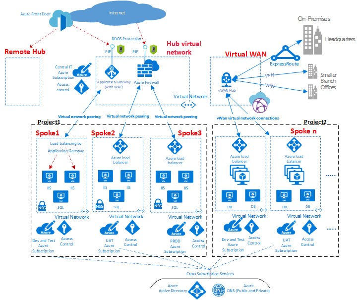
The definitive guide from the Azure Architecture Center explains the components and benefits in detail.
Hub-spoke network topology in Azure
This document is the canonical reference for the hub-spoke pattern in Azure.
Please read the following sections: Architecture and Concepts: Focus on the definitions of the Hub virtual network and Spoke virtual networks to solidify your understanding of their distinct roles. Scenario details and Potential use cases: This section answers the "why." Review the list of benefits and use cases to understand the architectural drivers for choosing this pattern, such as cost savings, workload isolation, and central control over security and connectivity.
Architecting Traffic Flow
Now that we have the structure, the critical architectural task is to design the traffic flow. The hub-spoke model provides powerful options for controlling how spokes communicate with the outside world and with each other.
Spoke-to-Spoke Communication
Since peering is non-transitive, how does a resource in Spoke A talk to a resource in Spoke B? By default, it can't. The hub-spoke model gives you two primary patterns to solve this, and your choice depends on the trade-offs between performance, security, and complexity.
Pattern 1: Route Traffic Through the Hub (The Standard Approach)
This is the most common pattern. You force all inter-spoke traffic to be routed through a central appliance in the hub, typically an Azure Firewall.
Here's how it works:
- You place a network virtual appliance (NVA), like Azure Firewall, in the hub VNet.
- On each spoke's subnets, you apply User-Defined Routes (UDRs).
- These UDRs tell the spoke's resources: "To reach the IP address range of another spoke, your next hop is the private IP address of the Azure Firewall in the hub."
The traffic flows from Spoke A, to the firewall in the hub, gets inspected against a central set of security rules, and is then forwarded to Spoke B. This provides a single point for security inspection and policy enforcement for all east-west traffic.
This next video provides an excellent whiteboard walkthrough of this exact process.
Hub and Spoke Enterprise-Scale Landing Zone Networking | Whiteboard Design & Setup Explained
This video visually demonstrates how the hub, spokes, firewall, and user-defined routes work together to control traffic flow.
Watch these key segments: Introducing the Hub: The narrator explains the need for a central firewall in a dedicated "Hub subscription." Peering and Routing: This is the core of the concept. Pay close attention to how VNet peering connects the spokes to the hub, and how UDRs are used to force traffic through the firewall.
Pattern 2: Direct Peering Between Spokes (The Exception)
While routing through the hub is the standard, sometimes two specific workloads have very high-bandwidth or low-latency communication needs. Routing through a firewall adds a small amount of latency. In these specific cases, you can create a direct peering connection between the two spokes that need this high-performance path.
This creates a hybrid or "partial-mesh" topology. It should be used judiciously to avoid negating the management benefits of the hub-spoke model.
The following resource provides an excellent comparison of these two patterns.
Virtual Network Connectivity Options and Spoke-To- ...
This article is perfect for your analytical style, as it explicitly lays out the patterns and trade-offs.
Please read the following sections: Spoke-to-spoke communication patterns: This introduces the concept of east-west traffic and frames the two patterns we're discussing. Pattern 1: Spokes directly connect to each other: Understand when and why you would use direct peering between spokes. Pattern 2: Spokes communicate over a network appliance: This reinforces the standard model of routing through the hub. Review the diagram showing traffic flowing through the central appliance.
Spoke to On-Premises: Gateway Transit
A final common requirement is for spokes to communicate with your on-premises datacenters. The hub-spoke model elegantly handles this with a feature called Gateway Transit.
Instead of deploying a costly VPN or ExpressRoute gateway in every spoke, you deploy one gateway in the hub. Then, you configure the VNet peerings to allow spokes to "transit" through the hub to use its gateway.
On the peering configuration from the hub to the spoke, you check "Allow gateway transit."
On the peering configuration from the spoke to the hub, you check "Use the remote virtual network's gateway."
This centralizes hybrid connectivity, reducing cost and management complexity. John Savill's first video provides a great visual for this.
Complete Overview of Azure Virtual Network Peering
Let's revisit the first video to see how gateway transit is configured.
Rewatch the segment from Gateway Transit. The diagram clearly shows how enabling gateway transit on the peering allows spokes to access on-premises networks via the hub's gateway.
Conclusion
In this lesson, we've moved from single, isolated networks to a scalable, enterprise-grade network architecture. You can now explain the fundamental patterns for connecting multiple VNets in Azure and the architectural decisions involved.
Here are the key takeaways:
- VNet Peering is the primary method for connecting two VNets, but it is non-transitive, which creates a scalability problem for mesh topologies.
- The Hub-Spoke architecture solves this by centralizing connectivity and shared services in a hub VNet, while isolating workloads in spoke VNets.
- This pattern provides centralized security, simplifies management, and reduces costs by sharing expensive resources like firewalls and gateways.
- Spoke-to-spoke communication is not enabled by default. It is typically achieved by using User-Defined Routes (UDRs) to force traffic through a central firewall in the hub, allowing for security inspection.
- Gateway Transit is a key peering feature that allows spokes to share the hub's VPN or ExpressRoute gateway for hybrid connectivity.
We've now established the "city plan" for our Azure environment. We know how to create individual "neighborhoods" (VNets with subnets) and how to connect them with "highways" (peering) through a central "downtown" (the hub). In our next lesson, we will look at how to manage the "traffic" within this city, exploring Azure's different load balancing options to distribute requests efficiently and ensure high availability for your applications.