Hello! Welcome to the first lesson of our eighth module, "Coil Construction, Assembly, and Diagnostics."
In our previous modules, we developed sophisticated theoretical models for the electromagnetic, mechanical, and thermal behavior of high-field magnets. We calculated field profiles, stress distributions, and thermal equilibria. However, all these calculations were based on an important assumption: that the coil is a geometrically perfect, monolithic object. Today, we begin the transition from this idealized theory to real-world manufacturing.
This lesson addresses the learning outcome: Describe precision winding techniques for mono-layer and multi-layer coils to ensure geometric accuracy. We will investigate how the neat, ordered arrays of conductors from our textbook diagrams are painstakingly realized in practice. Achieving this geometric accuracy is not merely an aesthetic goal; it is fundamental to a magnet's performance, reliability, and ultimate field strength.
1. The Challenge of Geometric Accuracy
Why is the physical arrangement of the wires so critical? A coil's geometry directly dictates:
- Magnetic Field: The field's strength and homogeneity depend on the precise location of every turn. Deviations from the planned geometry introduce field errors.
- Mechanical Stress: Under the immense Lorentz forces of a pulse, stresses must be distributed uniformly. Random gaps or misaligned wires create stress concentration points, which can become failure initiation sites.
- Thermal Performance: Tightly packed conductors provide a consistent path for heat to flow out to the cooling channels. Voids or gaps act as thermal insulators, trapping heat and potentially leading to local overheating and insulation failure.
The most basic winding method, often called "wild winding," involves simply feeding wire onto a rotating former. While fast and simple, the result is a disorderly arrangement with significant drawbacks.
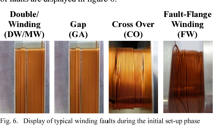
These imperfections lead to a low space factor—the ratio of the conductor's cross-sectional area to the total area of the winding window. A low space factor means less conductor in a given volume, which compromises the magnet's efficiency.
2. Orthocyclic Winding: The Ideal Pattern
To overcome the issues of wild winding, precision techniques aim for the most compact and orderly arrangement of round wires possible. This ideal is known as orthocyclic winding.

The principle of orthocyclic winding is twofold:
- Orthogonality: The majority of each turn is wound in a plane perpendicular (orthogonal) to the coil axis.
- Nesting: In multi-layer coils, the wires of each new layer settle into the grooves of the layer below it, creating a dense, hexagonally close-packed structure.
This method achieves the maximum theoretical space factor for round wires, which is approximately 91%. To understand the principles and benefits in more detail, let's turn to a classic technical paper on the subject.
The 'Philips Technical Review' paper on orthocyclic winding provides a foundational and highly detailed explanation of this technique. It clearly lays out the principles, challenges, and remarkable advantages of this precision method.
Please read the following sections from the paper: Introduction (pp. 365-367): Focus on the comparison between 'wild' winding and the motivation for developing a more precise method. Pay attention to the discussion of space factor and voltage distribution. Orthocyclic Coils (p. 367): Understand the core concept of orthogonal turns and nested layers. Crossovers (p. 368): Grasp the idea of the 'crossover,' the small section of each turn that advances the winding to the next position. Coil thickness and space factor (pp. 368-369): Note the calculation for the ideal space factor (\pi / (2\sqrt{3}) \approx 0.91) and how layers stack. Orthocyclic coils compared with types wound by other methods (pp. 374-375): This section summarizes the key benefits that justify the complexity of the method. Focus on permanence of shape, heat conduction, and electrical predictability.
As the paper highlights, the benefits of achieving this ordered structure are immense: a stable, predictable, and efficient coil. However, realizing this ideal in practice requires surmounting significant engineering challenges.
3. Practical Requirements for Precision Winding
The orderly stacking of layers in an orthocyclic coil is a self-propagating process, but only if the first layer is perfect and the materials meet stringent specifications. A tiny error in the first layer will be amplified in subsequent layers, quickly leading to a complete breakdown of the ordered pattern.
The Conductor Wire
The most critical parameter is the outer diameter of the insulated wire.
The Philips paper continues with a crucial discussion of the practical requirements for the wire and the winding mandrel. This section gets to the heart of the manufacturing challenge.
Please read the section titled 'The wire' (p. 370). Focus on: Tolerance Requirement: Understand the example calculation showing that for a 120-turn layer of 100 µm wire, the diameter tolerance must be within 0.17 µm. This demonstrates the extreme precision needed. Insulation: Note that 'enamel' (or modern polymer films like Kapton) is the only suitable insulation, as its thickness can be controlled more precisely than fiber wrappings. Redrawing: Learn about the technique of redrawing enamelled wire through a die to achieve a uniform outer diameter, and understand its consequences (hardening of the copper, increased resistance).
Modern pulsed magnets often use rectangular or square wire to maximize the space factor beyond what's possible with round wire. However, the principle remains the same: the dimensions of the insulated conductor must be controlled with extreme precision.
The Winding Mandrel and Process
The winding itself is a delicate mechanical ballet.
- Mandrel/Former: The coil is wound onto a high-precision, rigid metal mandrel. Its dimensions, particularly the distance between the flanges that define the winding length, must be machined to a tolerance comparable to that of the wire diameter.
- Orthogonal Feed: The wire must be fed onto the mandrel at a perfect 90° angle to the axis of rotation to ensure the turns lie flat. Special pivoting guide arms are used to maintain this angle as the winding progresses across the layer.
- Patterning the First Layer: This is the most critical step. For small-scale or prototype production, it can be done manually by a skilled operator. For larger production, a machine with a precisely controlled shuttle mechanism lays down the first layer with the correct pitch.
Test your understanding!
You are winding a single layer of 200 µm diameter wire. According to the Philips paper, a cumulative error of half a wire diameter is enough to disrupt the orthocyclic pattern in the next layer. If your wire supply has a consistent +0.5% oversize error, after approximately how many turns will this critical error be reached? Why is this so catastrophic for a multi-layer coil?
Show answer
- Calculate the error per turn:
- Wire diameter = 200 µm
- Error = +0.5% = 0.005 * 200 µm = 1 µm per turn.
- Calculate the critical cumulative error:
- Critical error = 0.5 * wire diameter = 0.5 * 200 µm = 100 µm.
- Calculate turns to reach critical error:
- Number of turns = Critical error / Error per turn = 100 µm / 1 µm/turn = 100 turns.
After only 100 turns, the winding is already at risk of failure. A turn may ride up on the previous one instead of lying flat, creating a bump. In a multi-layer coil, this single bump disrupts the perfect grooves for the next layer. The disorder propagates and amplifies through all subsequent layers, quickly destroying the orthocyclic pattern and reverting the coil to a "wild" wind with all its associated problems.
4. Creating a Monolithic Structure: Wet Winding and Impregnation
A perfectly wound coil is still just a collection of individual wires. To withstand the violent electromagnetic forces of a 50+ Tesla pulse, it must be transformed into a solid, monolithic composite structure. This is achieved by filling every microscopic void between the conductors with a high-strength polymer, typically an epoxy resin.
A common and effective technique is wet winding. During the winding process, the wire is continuously coated with liquid epoxy just before it is laid onto the mandrel. The tension of the winding helps to squeeze out excess epoxy, ensuring a high conductor-to-epoxy ratio.
After winding, the entire coil is cured, often in an oven at a specific temperature for several hours. This solidifies the epoxy, bonding all the turns together into a single, robust block. This process simultaneously provides mechanical integrity and enhances electrical insulation by eliminating air gaps where electrical discharge could occur.
Let's look at how these techniques are applied in a state-of-the-art pulsed magnet facility.
Pulsed-coil magnet systems for applying 10-30 Tesla ...
This paper from Sandia National Laboratories describes the construction of pulsed magnets for the Z-machine. It provides an excellent real-world example of the materials and techniques used in modern high-field coil fabrication.
Please read the three paragraphs in Section II that begin with 'Several considerations influenced the design and fabrication methods...' (bottom of p. 8, continuing on p. 9). Focus on these practical details: Conductor Choice: Note the use of square AWG #11 copper wire insulated with Kapton. Square wire naturally achieves a higher space factor than round wire. Fabrication Method: Identify the key phrase: 'wet-winding the magnet wire onto the Torlon or Delrin housing with Stycast 1264 epoxy'. Reinforcement: Observe that after winding, the coil is overwrapped with Zylon fiber, also using a wet-wind process with the same epoxy. This is a critical step for mechanical reinforcement that we will cover in a future lesson. Curing: Note the specific curing schedule mentioned ('accelerated cure at 150°F for 3 hours'). Housing Materials: Understand the rationale for choosing Torlon or Delrin over a material like G-10 for the coil former.
The process described—precision winding of polymer-insulated wire, wet-winding with epoxy, and external reinforcement—is the standard pathway for building robust, reliable pulsed magnets capable of surviving extreme conditions.
Conclusion
In this lesson, we have bridged the gap between the idealized coils of our theoretical models and the practical reality of their construction. We have seen that achieving the required geometric accuracy is a demanding process that hinges on meticulous attention to detail at every step.
Key Takeaways:
- Geometric accuracy in a coil is essential for predictable magnetic fields, uniform stress distribution, and effective cooling.
- Orthocyclic winding is the ideal pattern for round wires, achieving the highest possible space factor (~91%) by nesting turns in successive layers.
- Successful precision winding requires extremely tight tolerances on the conductor's outer diameter and the mandrel's dimensions.
- Modern high-field coils are made into monolithic structures using wet winding or vacuum impregnation with epoxy resin, which is then cured to create a solid, mechanically robust composite.
Next Lesson Preview:
The process of filling the gaps between wires with epoxy is so critical that it deserves its own lesson. While we've introduced the idea of wet winding, a more advanced technique is vacuum impregnation, which ensures that even the smallest voids are filled. In our next lesson, we will delve into the details of this process, including the choice of epoxies, the importance of removing all air, and the specific curing schedules required to achieve maximum mechanical strength.