Hello! Welcome to the first lesson in our module on Pulsed Power Systems and Control.
In our previous lesson, we established the three fundamental constraints on pulsed magnet performance: the mechanical, thermal, and electrical limits. We saw that the electrical limit, , is determined by the total energy stored in the power supply. This sets a hard ceiling on the achievable magnetic field, no matter how strong or thermally robust your coil is.
Today, we're going to flip that problem on its head. Instead of starting with a given capacitor bank and finding its field limit, we will start with a target magnetic field and determine the necessary specifications for the capacitor bank to generate it. This is a foundational step in the practical design of any pulsed magnet system.
Our learning outcome is to design the specifications for a capacitor bank, including total capacitance, voltage rating, and stored energy for a target field. We'll develop a clear workflow to move from a desired experimental condition to a concrete engineering specification.
1. From Target Field to Required Energy
Let's begin with the principle of energy conservation, which we touched upon in the last lesson. The initial electrical energy stored in the capacitor bank, , is converted into magnetic energy stored in the coil, , and energy dissipated as heat, .
A crucial figure of merit for the system is the energy transfer efficiency, , defined as the fraction of the initial electrical energy that is successfully converted into magnetic energy at the moment of peak field.
This efficiency is always less than 1 due to inevitable resistive losses in the coil, switches, and connecting busbars. A well-designed system might achieve an efficiency of 70-80%, while a less optimal one might be 50% or lower.
Our goal is to generate a target peak field, . We know the relationship between the peak magnetic energy in the coil, its inductance , and the peak current is:
We also know from our first module that the peak field is proportional to the peak current via the coil's geometry factor, : .
By substituting and into the energy equation, we can solve for the required stored energy in the capacitor bank:
This is our cornerstone equation. To specify the required energy, you need to know the coil's properties ( and ), the desired field (), and you must make an educated guess about the system's efficiency ().
2. The Capacitance vs. Voltage Trade-Off
Once we've calculated the required energy , we need to determine the specific values for capacitance () and charging voltage (). They are related by the familiar formula:
For a fixed energy requirement, this equation presents a fundamental design choice: do you use a high voltage and low capacitance, or a low voltage and high capacitance?
-
High-Voltage, Low-Capacitance Bank:
- Advantages: For a given energy, the capacitors are physically smaller and lighter. This can be critical for mobile or compact systems.
- Disadvantages: High voltage (>10 kV) poses significant safety risks and requires robust, expensive insulation for all components (coil, cables, switches) to prevent dielectric breakdown and arcing.
-
Low-Voltage, High-Capacitance Bank:
- Advantages: Safer to operate. Components rated for lower voltages are often more common and less expensive.
- Disadvantages: Requires enormous and physically massive capacitors. To deliver the same power, a lower voltage implies a much higher current (), demanding very thick busbars and high-current switches to handle the amperage and minimize resistive losses.
Let's examine a real-world design study that perfectly illustrates this trade-off.
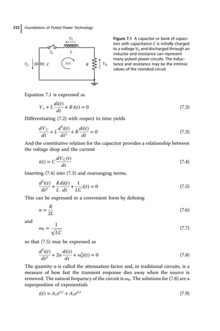
Modeling and Design of Magnetic Flux Compression ...
The following text, from a thesis on magnetic flux compression, provides an excellent case study. The author designs a capacitor bank to provide a 'seed' field for a generator, walking through the exact calculations we are discussing.
Please read Section 4.1, 'Capacitor Bank'. Pay close attention to: The initial discussion on the advantages of higher voltages. The author's choice of a low 20 V supply and the resulting 9 mF capacitance requirement. The assumption of 70% energy transfer efficiency. The final conclusion in the last paragraph about the physical size of the resulting capacitor bank, which highlights the major drawback of the low-voltage approach.
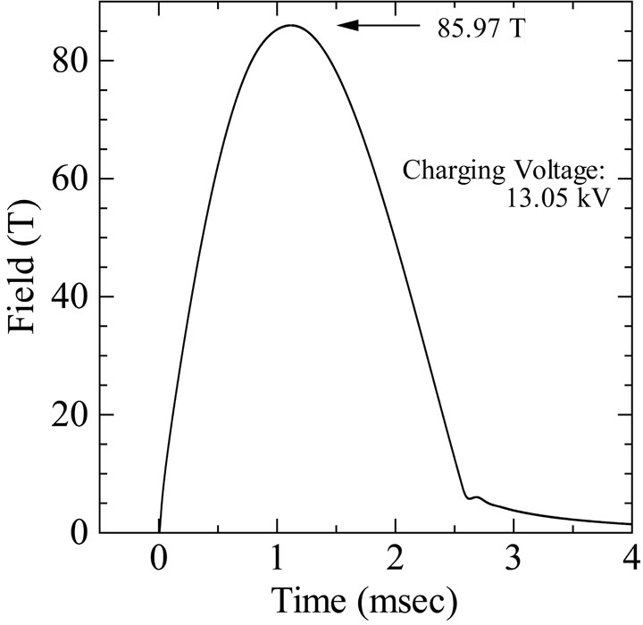
As you saw in the reading, the choice of a low 20V voltage led to a requirement for six very large capacitors, making the power supply much larger than the device it was powering. Most large-scale pulsed field laboratories, like LNCMI, opt for high-voltage systems (typically 10-24 kV) to store mega-joules of energy in a reasonably compact volume.
3. A Practical Design Workflow
We can now consolidate our discussion into a step-by-step workflow for specifying a capacitor bank.
Step 1: Define the Target Field ()
This is determined by the scientific goals of the experiment.
Step 2: Define the Coil Parameters ()
Use an existing coil design or an initial estimate from analytical models. For this step, we'll assume the coil is a given.
Step 3: Estimate the Energy Transfer Efficiency ()
Based on experience or prior simulations, choose a reasonable value. A good starting point for a well-matched system is often in the range of to .
Step 4: Calculate the Required Stored Energy ()
Use the formula derived earlier:
Step 5: Select a Charging Voltage ()
This is a key engineering decision based on the trade-offs discussed above. For high-field magnets, this is typically in the 10 kV to 25 kV range. Let's assume a voltage standard for our hypothetical lab.
Step 6: Calculate the Required Capacitance ()
Rearrange the energy formula:
Step 7: Final Specification
The final specification for the bank is the set of these three key parameters: {Total Stored Energy, Total Capacitance, Maximum Charging Voltage}.
Test your understanding!
You are tasked with designing a capacitor bank for a new pulsed magnet at your lab. The specifications are as follows:
- Target Field: T
- Coil Parameters: Inductance mH, Field Factor T/kA.
- System Efficiency: You estimate an efficiency of .
- Lab Standard Voltage: Your facility's capacitor banks are standardized to a maximum charging voltage of kV.
Calculate the required stored energy () in MJ and the total capacitance () in mF for the bank.
Show answer
First, let's ensure our units are consistent. The field factor is T/kA = T/A.
1. Calculate Required Stored Energy ()
Using our main formula:
So, the required stored energy is 1.67 MJ.
2. Calculate Required Capacitance ()
Now we use the energy and the lab's standard voltage to find the capacitance:
So, the required capacitance is 5.8 mF.
The final specification for the bank is: 1.67 MJ, 5.8 mF, rated for 24 kV.
Conclusion
In this lesson, we have developed a systematic approach to determining the top-level specifications for a capacitor bank based on a desired magnetic field.
Key Takeaways:
- The required stored energy () is directly proportional to the square of the target field () and the coil's inductance (), and inversely proportional to the system's efficiency ().
- For a given energy requirement, there is a fundamental trade-off between capacitance () and voltage (). High-voltage, low-capacitance systems are more compact but pose greater insulation challenges, while low-voltage, high-capacitance systems are safer but physically massive and involve extremely high currents.
- The design process follows a clear workflow: define the target, use coil parameters and efficiency to find the total energy, then choose a voltage to calculate the necessary capacitance.
Next Lesson Preview:
We've now defined the what—the total energy, capacitance, and voltage. But a 5 mF capacitor is not a single off-the-shelf component; it's an assembly of many individual units. The type of capacitor used is critically important. In our next lesson, we will evaluate different capacitor technologies (e.g., electrolytic, film) and select the appropriate type for a pulsed magnet application, considering crucial real-world properties like internal resistance (ESR) and inductance (ESL).