Hello! Welcome back to your course on high-field magnet design.
In our last lesson, we developed a detailed picture of the magnetic field vector, , both within the bore and, crucially, throughout the windings of a solenoid. We saw how the field is composed of a strong axial component and a radial component that becomes significant at the coil's ends.
Now, we will put that knowledge to work to address a central challenge in magnet design. Today's learning outcome is to calculate the Lorentz force distribution and resulting magnetic pressure within the coil windings. The immense forces generated are often the primary factor limiting the achievable magnetic field, as they can physically destroy the coil. Understanding their origin, distribution, and magnitude is the first step toward designing a structure that can contain them.
1. The Lorentz Force and Magnetic Pressure
The fundamental source of force on any current-carrying wire in a magnetic field is the Lorentz force. For a small segment of wire carrying current , the force is:
It is often more convenient to work with a continuous current density (in A/m²) and the corresponding force density (in N/m³):
This is a body force, meaning it acts throughout the entire volume of the conductor. To find the total force on a component, we must integrate this density over its volume.
A very useful and intuitive concept for understanding the overall effect of these forces is magnetic pressure. The magnetic field stores energy, and this energy density acts like a pressure pushing on the conductors that create it.
To build a strong intuition for this concept, let's watch a classic lecture segment from Prof. Walter Lewin.
8.02x - Module 10.01 - Pressure Due to a Magnetic Field in a Solenoid.
In this video, 'Pressure Due to a Magnetic Field in a Solenoid', Prof. Lewin provides a clear, step-by-step derivation of the outward force on a solenoid winding. He then connects this force to the concept of magnetic pressure and shows that this pressure is numerically equal to the magnetic energy density.
Please watch from 06:18 to 12:43. Pay close attention to: How he applies the Lorentz force law to a ring of current. The reasoning for using an average magnetic field at the wire's location. The final calculation of pressure and its equivalence to the magnetic energy density, B^2 / (2\mu_0).
As Prof. Lewin demonstrates, the magnetic pressure is given by:
This simple formula is incredibly powerful. For a 40 T field, typical of a high-end resistive magnet, the magnetic pressure is Pa, or about 637 MPa. This is comparable to the yield strength of many high-strength steels, giving you an immediate sense of the immense forces that need to be managed.
The following document provides a concise summary of these foundational concepts.
Mechanical Design of Superconducting Accelerator Magnets
The document 'Mechanical Design of Superconducting Accelerator Magnets' from the CERN Accelerator School offers a clear introduction to the electromagnetic forces in magnets.
Please read Section 2.1, 'Electromagnetic forces' (pages 2-3). This section formally defines the Lorentz force density and magnetic pressure, reinforcing the concepts from the video.
2. Deconstructing the Force: Radial and Axial Components
The magnetic pressure gives us a sense of the overall magnitude, but to design a robust magnet, we need to know the direction of the forces. Let's analyze the force density vector for a standard solenoid.
- Current Density : In a simple solenoid, the wire is wound in hoops, so the current flows in the azimuthal direction: .
- Magnetic Field : As we learned in the last lesson, the field inside the winding has two main components: a strong axial field and a weaker radial field that peaks at the coil ends: .
Now, let's compute the cross product:
Using the relations for cylindrical unit vectors ( and ), we get:
This result is profoundly important. It tells us the force has two distinct components:
-
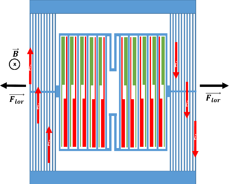
Radial Force (): The product of the azimuthal current and the strong axial field creates a purely outward radial force. This is often called hoop force, and it tries to burst the magnet open. This is the force responsible for the hoop stress we will study later.
-
Axial Force (): The product of the azimuthal current and the radial field creates an axial force. Since has opposite signs on either side of the magnet's midplane (it points outward at the ends), this force is directed inward, compressing the coil towards its center.
3. Calculating the Force Distribution
To calculate the precise force at every point in the winding, we must combine the field calculation methods from the last lesson with the Lorentz force law. The filamentary model you were introduced to is perfectly suited for this. The computational procedure is as follows:
- Discretize: The coil is modeled as a collection of N straight wire "filaments."
- Calculate Field: For each filament i, calculate the magnetic field at its center, which is the vector sum of the fields produced by all other filaments ().
- Calculate Force: With the current and vector length of the filament known, the force on that segment is calculated directly.
By repeating this for every filament, we can map the entire force distribution vector field throughout the coil.
The dissertation by Szabolcs Rembeczki, which we used in the last lesson, implements this exact method. Let's examine how it is described and what the results look like.
Design and Optimization of Force-Reduced High Field ...
Let's return to the Rembeczki dissertation. First, we will see how the filamentary approximation is used to calculate forces, and then we will analyze the resulting force distribution plots for different coil designs.
Please review the following sections: Section 3.3, 'Force Calculations' (pages 51-52): This section explicitly outlines the use of the Biot-Savart force law within the filamentary model. Note Figure 3.4, which visualizes the force vectors on the wire elements. Section 4.3, 'Forces on the Winding' (pages 72-78): This is a crucial section. Carefully compare the force component plots for a 'force-reduced' solenoid (Figure 4.9) and a 'regular' solenoid (Figure 4.10). Observe the differences in the radial (F_{rad}), axial (F_{ax}), and azimuthal (F_{azi}) forces. Section 5.3.1, 'Force Analysis' (pages 90-95): This extends the analysis to a 25 T multi-layer design. Study Figures 5.10 (radial), 5.11 (axial), and 5.12 (azimuthal) to see how forces are distributed across different layers.
From analyzing these plots, several key features of force distribution in a conventional solenoid become apparent:
- The radial force is large, positive (outward), and relatively constant along the central portion of the coil. It is the dominant force component.
- The axial force is negligible at the center () and grows to its maximum value at the ends, pointing inwards.
- The azimuthal force is negligible in a standard solenoid. (The large azimuthal forces seen in the "force-reduced" examples are a consequence of their special helical winding geometry, designed to trade radial force for azimuthal force).
Test your understanding!
In Rembeczki's dissertation, look at Figure 4.10 for the regular solenoid. Why is the axial force (, blue line) zero at the center () and maximum near the ends? Relate this to what you learned about the magnetic field distribution in the previous lesson.
Show answer
The axial force is given by . In the previous lesson (and from Maxwell's equations), we established that the radial field component is zero on the midplane () due to symmetry. Therefore, the axial force must also be zero at the center.
We also learned that grows in magnitude as we move from the center towards the ends of the coil, peaking near the physical ends of the winding. Since the axial force is directly proportional to , its distribution mirrors that of the radial magnetic field: zero at the center, and peaking at the ends.
Conclusion
In this lesson, we have connected the magnetic field profile of a coil directly to the mechanical forces it must endure. These forces are not just a theoretical curiosity; they are a tangible, destructive reality that every high-field magnet designer must confront.
Key Takeaways:
- The fundamental force is the Lorentz force, expressed as a density .
- The concept of magnetic pressure, , provides a powerful estimate for the scale of the forces involved.
- In a standard solenoid, the force vector can be decomposed into two main components:
- A radial (hoop) force () that tries to burst the coil.
- An axial force () that compresses the coil towards its midplane.
- Numerical methods, such as the filamentary model, are essential for calculating the detailed force distribution in complex coil geometries, allowing designers to map the force vectors throughout the windings.
Next Lesson Preview:
We have now calculated the forces. The next logical question is: what effect do these forces have on the materials of the coil? In the next lesson, we will begin our exploration of solid mechanics by defining stress, strain, and elastic modulus, and applying Hooke's law. This will allow us to translate the force distribution we calculated today into the internal stresses and physical deformations that the magnet components experience, which is the heart of mechanical design.