Welcome to the next lesson in our journey through Boolean algebra. In our previous session, we focused on representing logic functions in standardized canonical forms—Sum-of-Products (SOP) and Product-of-Sums (POS). These forms provide a unique algebraic fingerprint for any function, derived directly from its truth table.
Today, we will bridge the gap between this abstract algebra and the physical world of digital circuits. This lesson is all about the interplay between the three fundamental representations of a logic function: its truth table (the "what"), its Boolean expression (the "how"), and its gate-level circuit diagram (the "build"). Mastering the conversions between these forms is a cornerstone of digital design, allowing you to translate a functional specification into an implementable circuit, and vice-versa.
The Three Pillars of Logic Design
Every combinational logic function can be described in these three equivalent ways. You're already familiar with the basic building blocks—the logic gates. Let's start with a quick visual refresher of their symbols, expressions, and truth tables.

Our goal is to become fluent in translating a function from any one of these forms to another.
Path 1: From Truth Table to Boolean Expression
We touched upon this in the last lesson, and it's the crucial first step in synthesizing a circuit from a specification. A truth table defines the desired output for every possible combination of inputs. From this, we can derive a Boolean expression.
The most direct method is to generate one of the canonical forms:
- To get the Sum-of-Products (SOP) form: Identify all rows where the output is
1. For each of these rows, create a product term (minterm) that is true only for that specific input combination. The final expression is the logicalOR(sum) of all these product terms. - To get the Product-of-Sums (POS) form: Identify all rows where the output is
0. For each of these rows, create a sum term (maxterm) that is false only for that specific input combination. The final expression is the logicalAND(product) of all these sum terms.
The following reading from the "All About Circuits" textbook provides an excellent, practical walkthrough of this process using a "two-out-of-three" sensor logic problem.
Converting Truth Tables into Boolean Expressions
This article demonstrates how to derive both SOP and POS expressions directly from a truth table.
Please read the sections starting from "Using Sum-Of-Products" to see how an SOP expression is built and then simplified. Then, read the section "Using Product-Of-Sums" to understand the dual process for POS expressions. Finally, review the summary at the end of the page.
Path 2: From Boolean Expression to Gate-Level Diagram
Once you have a Boolean expression, drawing the corresponding gate-level diagram is a direct translation process. Each part of the expression maps to a specific gate:
- Variables (e.g., ) are the circuit's inputs.
- A NOT operation (e.g., or ) is implemented with an inverter (NOT gate).
- An AND operation (product, e.g., ) is implemented with an AND gate.
- An OR operation (sum, e.g., ) is implemented with an OR gate.
This leads to a natural structure for our canonical forms. An SOP expression like results in a two-level AND-OR circuit. The individual product terms (, ) are formed by AND gates, and their outputs are fed into an OR gate.
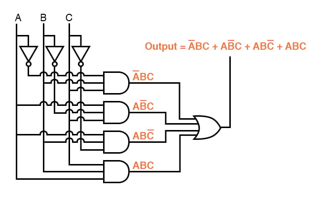
Similarly, a POS expression like results in a two-level OR-AND circuit. The sum terms are formed by OR gates, and their outputs are fed into an AND gate.
The following video demonstrates how to draw these diagrams from scratch.
Logic Gates, Truth Tables, Boolean Algebra AND, OR, NOT, NAND & NOR
This video from The Organic Chemistry Tutor provides clear, step-by-step instructions for converting Boolean expressions into circuit diagrams.
Please watch the segment from this section. It walks through how to draw diagrams for both an SOP expression ("sum of products") and a POS expression ("product of sums"), clearly explaining the mapping.
Path 3: From Gate-Level Diagram to Boolean Expression
To analyze an existing circuit, you perform the reverse process. You trace the circuit from the inputs to the output, writing down the Boolean expression for each gate's output along the way. It's essential to use parentheses to preserve the order of operations defined by the circuit's structure.
Let's return to the same video to see this process in action.
Logic Gates, Truth Tables, Boolean Algebra AND, OR, NOT, NAND & NOR
This segment demonstrates how to derive a Boolean expression by analyzing a gate-level diagram.
Watch the examples from this part of the video. The instructor methodically works through several circuits, showing how to build up the final expression one gate at a time.
Completing the Cycle
With these three conversion skills, you can now move between any of the representations. For example, how would you get a truth table from a gate diagram? You would first derive the Boolean expression from the diagram, and then evaluate that expression for all possible input combinations to fill out the truth table.
Let's walk through an example. Consider this circuit:
A simple combinational logic circuit.
-
Derive the Expression:
- The output of the NOT gate is .
- The output of the AND gate is .
- The output of the OR gate, which is the final output , is .
-
Create the Truth Table:
Now we evaluate for all 8 input combinations of A, B, and C.
| A | B | C | |||
|---|---|---|---|---|---|
| 0 | 0 | 0 | 1 | 0 | 0 |
| 0 | 0 | 1 | 1 | 0 | 1 |
| 0 | 1 | 0 | 1 | 1 | 1 |
| 0 | 1 | 1 | 1 | 1 | 1 |
| 1 | 0 | 0 | 0 | 0 | 0 |
| 1 | 0 | 1 | 0 | 0 | 1 |
| 1 | 1 | 0 | 0 | 0 | 0 |
| 1 | 1 | 1 | 0 | 0 | 1 |
We have now successfully converted from a gate diagram to a truth table by using the Boolean expression as an intermediate step.
Let's Practice
As you requested, here are a few problems to solidify your understanding. Try to solve them on your own before looking at the solution.
Problem 1: From Truth Table to Circuit
Given the following 3-variable truth table for a function , derive its canonical SOP expression and draw the corresponding two-level AND-OR gate-level circuit.
| A | B | C | G |
|---|---|---|---|
| 0 | 0 | 0 | 0 |
| 0 | 0 | 1 | 1 |
| 0 | 1 | 0 | 0 |
| 0 | 1 | 1 | 1 |
| 1 | 0 | 0 | 0 |
| 1 | 0 | 1 | 0 |
| 1 | 1 | 0 | 1 |
| 1 | 1 | 1 | 0 |
Solution
1. Derive the Canonical SOP Expression
We look for rows where . These are rows 1, 3, and 6.
- Row 1 (001): Minterm
- Row 3 (011): Minterm
- Row 6 (110): Minterm
The canonical SOP expression is the sum of these minterms:
2. Draw the Gate-Level Circuit
The expression has three product terms, so we need three 3-input AND gates. The outputs of these AND gates will feed into one 3-input OR gate. We also need inverters for the complemented variables.
The AND-OR circuit implementation for .
Problem 2: From Circuit to Expression and Truth Table
For the circuit shown below, derive the final Boolean expression for and then create its truth table.
A circuit with two OR gates and one AND gate.
Solution
1. Derive the Boolean Expression
Let's work from the inputs to the output.
- The output of the top OR gate is .
- The output of the bottom OR gate is .
- The final AND gate multiplies these two intermediate results.
The final expression is:
This is a POS form.
2. Create the Truth Table
We evaluate for all 8 input combinations.
| A | B | C | ||||
|---|---|---|---|---|---|---|
| 0 | 0 | 0 | 1 | 1 | 0 | 0 |
| 0 | 0 | 1 | 1 | 1 | 1 | 1 |
| 0 | 1 | 0 | 0 | 0 | 1 | 0 |
| 0 | 1 | 1 | 0 | 0 | 1 | 0 |
| 1 | 0 | 0 | 1 | 1 | 0 | 0 |
| 1 | 0 | 1 | 1 | 1 | 1 | 1 |
| 1 | 1 | 0 | 0 | 1 | 1 | 1 |
| 1 | 1 | 1 | 0 | 1 | 1 | 1 |
Conclusion
In this lesson, you have learned the essential skill of translating between the three primary representations of a logic function. This ability is fundamental to virtually all digital design and analysis.
Key Takeaways:
- A logic function can be fully described by a truth table, a Boolean expression, or a gate-level diagram.
- You can systematically derive a canonical SOP or POS expression from a truth table by focusing on the '1' or '0' outputs, respectively.
- A Boolean expression maps directly to a gate diagram: addition (+) is OR, multiplication (·) is AND, and complement (') is NOT.
- An SOP expression naturally forms an AND-OR circuit, while a POS expression forms an OR-AND circuit.
- You can derive the expression for a circuit by writing out the function of each gate, working from inputs to output.
We have now completed our exploration of Boolean algebra fundamentals and canonical forms. In the next lesson, we will explore a powerful and practical concept: universal gates. You will learn how NAND and NOR gates can be used to construct any logic function, a technique that drastically simplifies the physical implementation of digital circuits.