Welcome to the third lesson in our module on number systems. In our previous lesson, we dove into the mechanics of 2's complement arithmetic, seeing how it enables computers to perform subtraction using only addition circuitry—a core principle of efficient digital design. You practiced these calculations and learned to spot overflow errors, which occur when results exceed the system's fixed-bit range.
So far, our focus has been on representing numbers for computation. Today, we'll shift our perspective to explore binary codes designed for different, but equally important, purposes. We'll investigate three key codes: Binary Coded Decimal (BCD), Gray code, and Excess-3 code. These are crucial for tasks like interfacing with human-readable displays, preventing errors in mechanical sensors, and simplifying certain arithmetic operations. This lesson will broaden your understanding of how binary patterns can be structured to solve specific engineering challenges.
Binary Coded Decimal (BCD): Bridging the Human-Computer Gap
While pure binary representation is the most efficient for a computer's internal arithmetic, it's not very intuitive for humans. When you look at a digital clock or a voltmeter, you expect to see decimal digits (0-9), not long strings of binary. Binary Coded Decimal (BCD) serves as a convenient middle ground.
The structure of BCD is straightforward: instead of converting the entire decimal number to a single binary value, each decimal digit is individually converted to its 4-bit binary equivalent.
The most common form of BCD is the "8421 code," where the bits have the standard binary weights of .
The following video from Neso Academy provides a clear introduction.
Binary Coded Decimal (BCD) Code
This video explains the fundamental concept of BCD, showing how it represents decimal digits and why it's different from straight binary.
Please watch the following segments: What is BCD? This part defines the code, its 8421 weighting, and clarifies the difference between a decimal digit and a decimal number. BCD representation. This shows the 4-bit codes for decimal digits 0 through 9. Converting to BCD. This section demonstrates how to convert multi-digit decimal numbers into BCD.
As the video explained, to represent a number like 397 in BCD, you would encode each digit separately:
- 3 becomes
0011 - 9 becomes
1001 - 7 becomes
0111
So, the BCD representation of 397 is 0011 1001 0111.
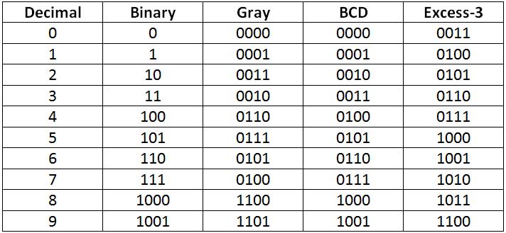
BCD vs. Straight Binary
It's important to understand the trade-offs of using BCD.
[PDF] binary coded decimal (BCD):
This document provides a concise summary of BCD, contrasting it with straight binary and highlighting its main use case.
Please read the first section, titled "1- Binary Coded Decimal (BCD)". Start from the beginning and read down to the paragraph that begins with this text. Pay close attention to the example comparing the representation of 137 in both straight binary and BCD.
The key takeaway is that BCD is less efficient in terms of storage. The number 137 requires only 8 bits in straight binary (10001001) but 12 bits in BCD (0001 0011 0111). However, this inefficiency is often a worthwhile price for the ease of conversion to and from decimal displays, which is why you find BCD in devices like digital multimeters, counters, and clocks.
Because BCD uses 4 bits to represent 10 digits (0-9), there are six unused or invalid 4-bit combinations: 1010 through 1111. In a pure BCD system, these bit patterns should never occur.
Gray Code: Preventing Transitional Errors
Imagine a rotating mechanical shaft whose angle you need to measure digitally. A common way to do this is with a disc attached to the shaft, marked with concentric rings of dark and light segments representing binary bits, which are read by optical sensors.
If you used standard binary code, a transition from, say, decimal 3 (011) to 4 (100) would require three bits to change simultaneously. In the physical world, these changes are never perfectly simultaneous. If the sensors read the state during this brief transition, they might read an intermediate, incorrect value like 111 (7) or 101 (5) before settling on 100. This can cause significant errors in position-sensitive systems.
Gray code brilliantly solves this problem. Its defining feature is that only a single bit changes between any two consecutive code words.
This Neso Academy video introduces Gray code and its unique properties.
Watch the beginning of the video, from the introduction, which explains the "unit distance" property that makes Gray code so useful.
Looking back at the comparison table, you can trace this property. Going from 7 (0100 in Gray) to 8 (1100 in Gray), only the most significant bit changes. Compare that to the standard binary transition from 7 (0111) to 8 (1000), where all four bits flip!
Converting Between Binary and Gray Code
Since processors work with binary, you need to be able to convert between binary and Gray code. The process is based on the XOR (Exclusive OR) operation.
The same video provides a step-by-step guide for both conversion directions.
Binary to Gray: Watch the segment from this timestamp. Gray to Binary: Watch the segment from this timestamp.
Let's summarize the rules:
Binary to Gray Conversion:
- The Most Significant Bit (MSB) of the Gray code is the same as the MSB of the binary number.
- Moving from left to right, add (XOR) each adjacent pair of binary bits to get the next Gray code bit. Discard any carries.
Example: Convert binary 1011 to Gray.
- MSB:
1(same as binary MSB) - Next bit:
- Next bit:
- LSB:
Result:1110
Gray to Binary Conversion:
- The MSB of the binary number is the same as the MSB of the Gray code.
- Moving from left to right, add (XOR) the most recently generated binary bit to the next Gray code bit.
Example: Convert Gray 1110 to binary.
- MSB:
1(same as Gray MSB) - Next bit:
- Next bit:
- LSB:
Result:1011
For more worked-out examples, you can refer to the "Gray Code" section in the University of Anbar document.
Excess-3 Code: Simplifying Decimal Arithmetic
The final code we'll discuss is Excess-3 (XS-3) code. Like BCD, it's a 4-bit code used to represent decimal digits. As its name suggests, an Excess-3 code word is generated by taking the decimal digit, adding 3, and then converting that sum to its 4-bit binary representation.
Example: To find the Excess-3 code for decimal 5:
- Add 3:
- Convert to 4-bit binary:
1000
So, the XS-3 code for 5 is1000.
[PDF] binary coded decimal (BCD):
This section of the document defines Excess-3 code and shows the complete code table.
Please read the short section titled "3- Excess-3 Code" down to the heading for "Alphanumeric Code".
The main advantage of Excess-3 code is that it is self-complementing. This means that the 1's complement of an Excess-3 code word gives the 9's complement of the corresponding decimal digit.
Let's verify this:
- Decimal 2 is
0101in Excess-3. - The 9's complement of 2 is 7. Decimal 7 is
1010in Excess-3. - Notice that
1010is the bitwise 1's complement of0101.
This property was useful in older computing systems because it simplified the hardware required to perform decimal subtraction.
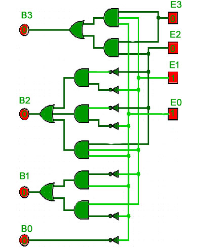
Like BCD, converting between BCD and Excess-3 is a common operation. The circuit below shows a hardware implementation for a BCD-to-Excess-3 converter. You'll learn how to design circuits like this from scratch using Karnaugh maps in a later module. For now, it's useful to see how these abstract codes translate into physical logic gates.
Practice Problems
To solidify your understanding, try these conversion problems. Refer back to the conversion rules and tables as needed.
- Convert the decimal number
48to BCD. - Convert the binary number
1101to Gray code. - Convert the Gray code
1001to binary. - Convert the decimal number
62to Excess-3 code.
Self-Correction and Reflection:
- For BCD and Excess-3, remember to convert digit by digit.
- For Gray code conversions, be careful with the XOR rules. For Gray-to-Binary, remember you are XORing with the previously calculated binary bit, not the adjacent Gray code bit.
Solutions
1. Decimal 48 to BCD:
4is01008is1000- Result:
0100 1000
2. Binary 1101 to Gray code:
- MSB:
1 - Next bit:
- Next bit:
- LSB:
- Result:
1011
3. Gray code 1001 to Binary:
- MSB:
1 - Next bit:
- Next bit:
- LSB:
- Result:
1110
4. Decimal 62 to Excess-3 code:
- For
6: , which is1001in binary. - For
2: , which is0101in binary. - Result:
1001 0101
Conclusion
In this lesson, we explored a set of essential binary codes that serve purposes beyond simple arithmetic. You learned that the choice of a particular code is a design decision driven by specific application requirements.
Here are the key takeaways:
- Binary Coded Decimal (BCD) is a weighted code that represents each decimal digit with a 4-bit binary number, making it ideal for human-facing interfaces like digital displays.
- Gray Code is a non-weighted code where only one bit changes between successive values. This "unit-distance" property is critical for preventing errors in electro-mechanical and analog-to-digital systems.
- Excess-3 Code is a non-weighted, self-complementing code derived by adding 3 to each decimal digit. Its self-complementing nature simplifies the hardware for decimal subtraction.
In our next and final lesson of this module, we will address another critical aspect of digital systems: reliability. You will learn how to detect and even correct single-bit errors in data using the principles of Hamming codes.