Welcome to the final lesson of our first module. In our last session, we explored specialized binary codes like BCD, Gray, and Excess-3, each tailored for a specific engineering task, from user displays to preventing mechanical sensor errors. We saw that how we represent data is a critical design choice. Today, we address one of the most fundamental challenges in digital systems: the reliability of data.
When data is transmitted over a wire or stored in memory, it's susceptible to noise, radiation, or other physical effects that can cause a bit to flip from 0 to 1, or vice versa. A single flipped bit can corrupt a number, an instruction, or a pixel, leading to system failure. In this lesson, you will learn about Hamming code, a brilliant and efficient method not only to detect that a single-bit error has occurred but also to pinpoint its exact location and correct it automatically. This principle is a cornerstone of reliable computing, used in everything from satellite communications to the ECC (Error-Correcting Code) memory in high-reliability servers.
The Limits of Simple Parity
The simplest form of error detection is adding a single parity bit to a data word. For example, in an even parity scheme, the parity bit is set to 0 or 1 to make the total number of 1s in the entire word (data + parity) even.
- Data:
1011001(four 1s - already even) -> Parity bit is0. Transmitted word:1011001**0**. - Data:
1100011(five 1s - odd) -> Parity bit is1. Transmitted word:1100011**1**.
If the receiver gets a word with an odd number of 1s, it knows a single-bit error occurred. However, it doesn't know which bit flipped, so it can't correct the error. Furthermore, if two bits flip, the parity remains even, and the error goes completely undetected. We need a more robust system.
Hamming Distance and Error Correction
The power of an error-correcting code lies in the "distance" between valid code words. This is formalized as the Hamming distance, which is simply the number of bit positions in which two binary words of the same length differ.
1011and10**0**1have a Hamming distance of 1.0**1**1**0**and0**0**1**1**have a Hamming distance of 2.
To correct errors, we need to choose our valid code words to be far apart. If a single-bit error occurs, the corrupted word will still be "closer" to the original correct word than to any other valid word.
[PDF] ERROR CORRECTION: HAMMING CODES
This document provides an excellent, intuitive introduction to the concept of Hamming distance and its relationship to error detection and correction.
Please read the first part of the document, focusing on these two key ideas: Start from the beginning and read about the definition of Hamming distance. Continue reading through the examples of 1-bit, 2-bit, and 3-bit codes, paying close attention to the visual analogies (line, square, cube). Read the section that summarizes the general principles relating minimum distance to detection and correction capabilities. The key takeaway is that a minimum distance of 3 is required to correct single-bit errors.
As you've read, a code with a minimum Hamming distance of 3 between any two valid code words can detect and correct any single-bit error. This is the foundation of the standard Hamming code.
Constructing a Hamming Code (Encoding)
Richard Hamming's insight was to use multiple, overlapping parity bits. Each parity bit checks a different subset of the data bits. When an error occurs, the pattern of "failed" parity checks (called the syndrome) uniquely identifies the position of the faulty bit.
How Many Parity Bits are Needed?
Let's say we have data bits and we add parity bits. The total length of the code word is . These parity bits must be able to identify which of the positions is in error, plus one more state for "no error". So, the bits must be able to represent at least different states. This gives us the fundamental relationship for Hamming codes:
Since , we can rewrite this as:
This formula tells you the minimum number of parity bits () required for a given number of data bits (). For example, if you have 4 data bits (), you'll find that you need parity bits, because . This results in the common (7,4) Hamming code (7 total bits, 4 data bits).
The following video explains this relationship clearly.
How Hamming Code Corrects the Error | Hamming Code Explained
This video from ALL ABOUT ELECTRONICS derives the condition for the number of required parity bits.
Watch the segment from this timestamp that explains how the formula 2^k \ge m + k + 1 is derived.
The Encoding Process
The standard procedure for creating a Hamming code is as follows:
-
Position the Parity Bits: Number the bit positions starting from 1. The parity bits () are placed in positions that are powers of two (1, 2, 4, 8, etc.). The data bits () fill the remaining slots.
-
Determine Parity Groups: Each parity bit is responsible for checking a unique set of positions (including its own). The rule is:
- checks all bit positions whose binary representation has a
1in the least significant bit (positions 1, 3, 5, 7, 9, 11, ...). - checks all bit positions whose binary representation has a
1in the second bit position (positions 2, 3, 6, 7, 10, 11, ...). - checks all bit positions whose binary representation has a
1in the third bit position (positions 4, 5, 6, 7, 12, ...). - And so on.
- checks all bit positions whose binary representation has a
-
Calculate Parity Bit Values: For each parity group, calculate the value of the parity bit to satisfy the chosen parity scheme (typically even parity). This is done by taking the XOR of all the data bits in that group.
The next video segment will walk you through this entire encoding process for a (7,4) code.
How Hamming Code Corrects the Error | Hamming Code Explained
This segment demonstrates the full encoding process with a clear example.
Watch from the encoding section. Pay close attention to how the parity bits are placed and how the groups are formed to calculate the values of P1, P2, and P3 (which he calls P3, but is in position 4).
Detecting and Correcting an Error (Decoding)
Now for the most powerful part. When a receiver gets a Hamming-coded word, it performs the following steps:
-
Recalculate Parity: The receiver re-calculates the parity for each group, this time including the received parity bit in the check. For each group, it computes a check bit (). If the parity is correct (e.g., it's even for an even parity system), the check bit is
0. If the parity is incorrect, the check bit is1. -
Form the Syndrome: The check bits, ordered from highest to lowest (), form a binary number called the syndrome.
-
Locate the Error: The decimal value of the syndrome is the exact position of the bit that is in error!
- If the syndrome is
000, there is no error. - If the syndrome is
101(decimal 5), then bit 5 is wrong.
- If the syndrome is
-
Correct the Error: To correct the error, simply flip the bit at the identified position.
The following video provides a perfect, concise demonstration of this decoding and correction process.
Hamming Code | Error Correction
This video from Neso Academy walks through a complete example of detecting and correcting a single-bit error in a received 7-bit Hamming code.
Please watch the entire video from start to finish. It clearly demonstrates how to check each parity group, form the syndrome from the results, and use the syndrome's value to locate and flip the erroneous bit.
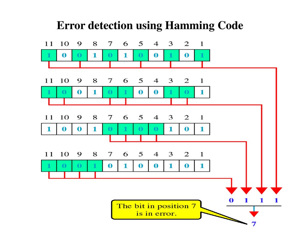
The image below provides a great static summary of this process. It shows a received 11-bit code, the four parity checks being performed, the resulting syndrome 0111, and how this value (decimal 7) correctly points to the bit in position 7 as the error.
A Complete Worked Example: (12,8) Hamming Code
Let's apply these principles to a slightly larger example. We want to transmit the 8-bit data word 10011101.
1. Determine Parameters:
- Data bits .
- Using , we need to find .
- If , (False).
- If , (True).
- So we need parity bits. The total code word will have bits. This is a (12,8) Hamming code. The parity bits will be .
2. Encoding:
-
First, lay out the 12 positions, placing the data bits (MSB to LSB) in the non-power-of-two slots.
- Positions: 12 11 10 9 8 7 6 5 4 3 2 1
- Type: D D D D P8 D D D P4 D P2 P1
- Data: 1 0 0 1 1 1 0 1
-
Now, calculate the parity bits for even parity (XOR of the data bits in each group):
- P1 (checks 3, 5, 7, 9, 11): . So, .
- P2 (checks 3, 6, 7, 10, 11): . So, .
- P4 (checks 5, 6, 7, 12): . So, .
- P8 (checks 9, 10, 11, 12): . So, .
-
The final transmitted code word is:
- Pos: 12 11 10 9 8 7 6 5 4 3 2 1
- Bit: 1 0 0 1 0 1 1 0 1 1 1 1
3. Decoding with an Error:
- Suppose during transmission, bit 6 flips. The received word is:
- Pos: 12 11 10 9 8 7 6 5 4 3 2 1
- Bit: 1 0 0 1 0 1 0 0 1 1 1 1
- The receiver calculates the check bits (syndrome):
- C1 (checks 1, 3, 5, 7, 9, 11): . (Parity is even, OK). .
- C2 (checks 2, 3, 6, 7, 10, 11): . (Parity is odd, FAIL). .
- C4 (checks 4, 5, 6, 7, 12): . (Parity is odd, FAIL). .
- C8 (checks 8, 9, 10, 11, 12): . (Parity is even, OK). .
- The syndrome word is .
- The decimal value of
0110is 6. The error is in bit position 6. - The receiver flips bit 6 from
0back to1, perfectly restoring the original code word.
Practice Problem
Now it's your turn. A (7,4) Hamming code is generated using even parity. The 4-bit data word to be sent is 1101.
- Generate the 7-bit Hamming code that should be transmitted.
- Suppose that after transmission, the receiver gets the word
0111101. Calculate the syndrome to find the error, and state the corrected 7-bit code word.
Solution
1. Encoding 1101
- Data bits:
- Layout:
- Pos: 7 6 5 4 3 2 1
- Type: D7 D6 D5 P4 D3 P2 P1
- Data: 1 1 0 1
- Calculate Parity Bits (Even Parity):
- P1 (checks 3, 5, 7): . So, .
- P2 (checks 3, 6, 7): . So, .
- P4 (checks 5, 6, 7): . So, .
- Transmitted Code:
1100110(from position 7 to 1).
2. Decoding 0111101
- Received Word:
- Pos: 7 6 5 4 3 2 1
- Bit: 0 1 1 1 1 0 1
- Calculate Syndrome (Check bits C4, C2, C1):
- C1 (checks 1, 3, 5, 7): . (Parity is odd -> FAIL). C1=1.
- C2 (checks 2, 3, 6, 7): . (Parity is even -> OK). C2=0.
- C4 (checks 4, 5, 6, 7): . (Parity is odd -> FAIL). C4=1.
- Syndrome: .
- The decimal value of
101is 5. The error is in bit position 5. - The received bit at position 5 is
1. We must flip it to0. - Corrected Code:
0101101.
Conclusion
This lesson concludes our first module on number systems and codes. You've now seen how binary data can be structured for arithmetic (2's complement), for interfacing (BCD), for preventing transitional errors (Gray code), and now for ensuring data integrity (Hamming code).
Here are the key takeaways from our study of Hamming codes:
- Simple parity can detect single-bit errors but cannot correct them.
- Hamming codes increase the Hamming distance between valid code words, allowing for both detection and correction. A minimum distance of 3 allows for single-bit error correction.
- The encoding process involves adding parity bits at power-of-two positions, where .
- The decoding process involves calculating a syndrome whose binary value directly points to the position of the single erroneous bit.
With this foundation, we are ready to move from representing data to manipulating it. In our next module, we will dive into Boolean Algebra, the mathematical language that governs the behavior of all logic gates and forms the bedrock of digital circuit design.