Welcome back! In our previous lesson, we surveyed the main applications of industrial machine vision, exploring what these systems are tasked with—from detecting microscopic defects to guiding robotic arms. This gave us a clear picture of the problems that industrial vision solves on the factory floor.
Now, we will shift our focus from the "what" to the "how." This lesson deconstructs a typical industrial vision system to examine its fundamental building blocks. Fulfilling your goal to understand practical system design, we will go beyond theory to look at the hardware and interfaces that make these applications possible. By the end of this lesson, you will be able to explain the distinct roles of the five core components: lighting, optics, the camera, the processing unit, and the communication interface.
The Anatomy of an Industrial Vision System
At its heart, an industrial vision system is a carefully engineered set of components working in concert to acquire and interpret an image, ultimately leading to an automated decision. Unlike general-purpose computer vision, where you might use a standard webcam in an uncontrolled environment, every piece of an industrial system is deliberately chosen to optimize for reliability, speed, and precision.
The diagram below illustrates the key components and the factors that influence their selection. We will use this as a roadmap for our lesson, exploring each element in detail.
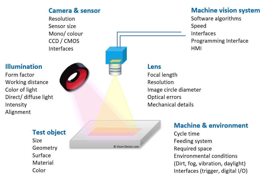
To see how these parts interact in a typical workflow, watch this brief animation from RealPars.
Introduction to Machine Vision for Controls Engineers
This clip from "Introduction to Machine Vision for Controls Engineers" shows the sequence of events in an automated inspection.
Watch the segment from this section. It demonstrates the interplay between the PLC, the part sensor, the camera, the industrial PC (IPC), and the final decision-making process.
As you saw, the process is a tightly choreographed sequence. Now, let's break down each component responsible for making it happen, starting with what is arguably the most critical element.
1. Illumination: Engineering the Light
In industrial vision, the mantra is "control everything you can." Lighting is the most powerful tool for controlling the appearance of the object being inspected. The goal is not simply to make the object bright, but to create the highest possible contrast between the features of interest (e.g., a defect) and the background. Good lighting can turn a difficult software problem into a trivial one.
This video makes a compelling case for why lighting is so crucial and demonstrates several key techniques.
The Secret to Machine Vision: Lighting | Machine Vision pt4 | Breen Machine Automation Services
In "The Secret to Machine Vision: Lighting," the presenter provides a highly practical, hands-on look at industrial lighting techniques.
Please watch the following segments: The introduction, which declares lighting as the most important part of a vision project. Ambient light problems, which shows why relying on factory lighting is a bad idea due to flicker. Glare and diffusion, demonstrating how to manage reflections from shiny surfaces. Side lighting, a technique to make surface textures and engravings "pop." Backlighting, which creates a high-contrast silhouette perfect for dimensional measurement. As you watch, consider how each technique simplifies the subsequent image analysis task.
In addition to the techniques shown, the video also addresses a fundamental choice: color vs. monochrome. Watch this next short clip from the same video.
The Secret to Machine Vision: Lighting | Machine Vision pt4 | Breen Machine Automation Services
This segment explains the preference for monochrome cameras and shows how to use colored light to differentiate colors.
First, watch the explanation of why monochrome is the default in industry. Then, see the demonstration of how colored light and filters can make specific colors stand out to a black-and-white camera.
The key takeaway is that by using red, blue, infrared, or UV light, you can manipulate contrast in ways that are impossible with a standard white light and color camera. This is a core principle of industrial imaging.
To solidify your understanding of these techniques, please read the following section from Emergent Vision Technologies, which provides concise definitions and diagrams.
Understanding the Anatomy of a Machine Vision System
This article breaks down the components of a vision system. We will return to it several times.
Start by reading the section titled Lighting, which recaps the different geometries like front, back, bright-field, and dark-field lighting.
2. Optics: The Lens
Once the scene is properly illuminated, the lens is responsible for gathering the reflected or transmitted light and focusing it precisely onto the camera's sensor. The choice of lens determines the field of view (FoV)—how much of the scene the camera can see—and the working distance—the distance from the lens to the part.
Unlike consumer camera lenses with autofocus, industrial lenses are almost always fixed-focus and often prime (fixed focal length). This mechanical simplicity ensures that once the system is set up and focused, it stays that way, providing the stability and repeatability required for metrology and consistent inspection.
Understanding the Anatomy of a Machine Vision System
Now, let's look at the "Lens" section in the same article.
Read the section titled Lens. Focus on understanding the definitions of Angle of View, Field of View, Object Distance, and Focal Length. These parameters are interconnected and form the basis of optical calculations we will perform in a later module.
3. The Camera and Sensor
The camera is the heart of the system, housing the image sensor that performs the magic of converting light (photons) into a digital image (pixel values). Your familiarity with computer vision gives you an intuitive understanding of concepts like resolution and frame rate. In an industrial context, these are critical design parameters with direct cost and performance implications.
Key specifications for an industrial camera include:
- Sensor Technology: While CCD sensors were once common, CMOS is now the dominant technology, offering higher speeds and better integration.
- Resolution: The number of pixels. Higher resolution allows for finer detail inspection or a larger field of view, but comes at the cost of higher data rates and more expensive lenses.
- Monochrome vs. Color: As discussed, monochrome sensors are preferred for most inspection and measurement tasks due to their higher effective resolution and light sensitivity.
- Frame Rate: The number of images captured per second. This must be fast enough to keep up with the production line's cycle time.
- Shutter Type: Global shutter, which exposes the entire sensor at once, is essential for capturing sharp images of moving objects without distortion. This is a key difference from the rolling shutters found in many consumer cameras.
Understanding the Anatomy of a Machine Vision System
Continuing with the same resource, let's examine the camera itself.
Please read the section titled Camera. Pay attention to the description of the image sensor's function and the definitions of the key digital imaging concepts.
4. The Processing Unit
The processing unit is the brain of the operation. It receives the digital image from the camera and runs the software algorithms—whether traditional methods like blob analysis or a deep learning model—to perform the inspection, measurement, or guidance task. This component is where your expertise as a software developer is most directly applicable.
Processing units in industrial vision come in several forms:
- Smart Cameras: The processor (often an FPGA or a small SoC) is integrated directly into the camera housing. They are self-contained and ideal for simpler, distributed tasks.
- Industrial PCs (IPCs) or Vision Controllers: Ruggedized, fanless computers designed for the factory floor. They offer significant processing power (often with GPUs) to handle complex algorithms or images from multiple high-speed cameras.
- Embedded Systems: Boards like the NVIDIA Jetson series are increasingly used to deploy deep learning models at the edge, offering a powerful and compact solution.
Understanding the Anatomy of a Machine Vision System
Let's look at the computing hardware options.
Read the section on Computing Platforms. This will give you a visual reference for the different types of hardware that run the vision software.
5. The Communication Interface
Finally, all these components must talk to each other. The communication interface defines both the physical connection (cabling) and the software protocol for transmitting data.
- The camera must send a high-bandwidth stream of image data to the processing unit.
- The processing unit must communicate the pass/fail result to the wider factory automation network, typically to a Programmable Logic Controller (PLC), which might then trigger a robotic arm or a pneumatic rejector.
This communication layer is critical for integrating the vision system into the production line.
5GigE Cameras for High Speed Vision Systems - LUCID Vision Labs
This article from LUCID Vision Labs provides an excellent comparison of modern camera interface standards.
Find and study Table 1: Interface Comparison. This table is a goldmine of practical information. Compare the different standards (e.g., GigE, USB, CoaXPress) on their maximum speed, cable length, and relative cost. Note why GigE Vision (the various BASE-T standards) represents a sweet spot for many applications.
The physical cable is only half the story. Software standards are needed to ensure that a camera from one manufacturer can talk to a software library from another. This is where standards like GigE Vision and GenICam come in.
- GigE Vision is a standard protocol for transmitting image data and control signals over Ethernet.
- GenICam (Generic Interface for Cameras) provides a standardized way to name and access camera features (e.g.,
ExposureTime,Gain), regardless of the manufacturer or interface technology.
For communication with the rest of the factory, a higher-level standard is needed. This is the role of OPC UA (Open Platform Communications Unified Architecture). It is a modern, platform-independent framework that allows machines, devices, and enterprise systems to exchange information in a structured way.
The image below contrasts the old, rigid "Automation Pyramid" with the flexible, networked communication enabled by OPC UA. A smart camera is no longer at the bottom of a strict hierarchy; it is a node in a network that can communicate directly with any other system component.

This shift is fundamental to the concept of Industry 4.0, and it's what allows a vision system to seamlessly report inspection statistics to a plant management dashboard while simultaneously telling a PLC to reject a faulty part.
Conclusion
In this lesson, we have dissected the industrial vision system into its five essential components. You now understand the specific function of each part and the key considerations that guide their selection and integration.
Key Takeaways:
- Illumination is about creating contrast to make features visible, not just making the scene bright. It is the most critical step in simplifying the vision task.
- Optics (Lenses) are chosen for stability and repeatability, determining the system's field of view and working distance.
- The Camera & Sensor convert light into a digital signal. Key choices involve trade-offs between resolution, speed, and sensitivity (monochrome vs. color).
- The Processing Unit is the system's brain, ranging from all-in-one smart cameras to powerful industrial PCs, running the analysis software.
- Communication Interfaces are the system's nervous system, using physical standards (like GigE) and protocol standards (like GigE Vision, GenICam, and OPC UA) to connect components and integrate with the factory.
These components are not chosen in isolation; they form an interdependent system where a decision about one part (e.g., a high-resolution sensor) has cascading effects on others (requiring a higher-quality lens, a faster interface, and more processing power).
In our next lesson, we will build directly on this foundation by taking a deeper dive into the most important industrial vision communication standards we just introduced: GigE Vision, GenICam, and OPC UA. We will explore how these protocols work and why they are the key to building flexible, interoperable, and powerful vision systems.