Welcome to the next lesson in our journey through LLVM's Intermediate Representation. In the past two lessons, we've established a solid foundation: you can now read the basic structure of IR, including functions and basic blocks, and you can identify the rich set of data types that describe every value. Now, we'll connect these concepts to see how LLVM represents program logic that isn't linear.
Today's objective is to learn how to trace control flow in LLVM IR using branch and phi instructions. These two instruction types are the fundamental mechanisms for building everything from simple if statements to complex loops. Mastering them is essential for understanding the logic of any non-trivial function you'll encounter while debugging or developing within LLVM. We will see how the br instruction directs the flow of execution and how the phi instruction elegantly solves the problem of merging values from different paths, a direct consequence of the Static Single Assignment (SSA) form.
The Challenge of Merging Paths in SSA
As you know, LLVM IR is in SSA form, meaning every virtual register is assigned a value exactly once. This simplifies many optimizations. But what happens when control flow merges? Consider a simple if-else statement where a variable x is assigned a different value in each branch. After the if-else, which value of x should be used? We can't simply re-assign x, as that would violate the single-assignment rule.
This is the central problem that control flow instructions must solve. The following video provides an excellent introduction to SSA and clearly illustrates this exact challenge.
Compiler Design Module 70 : Static Single Assignment IR
This video from the "compilerai" channel explains the motivation for SSA and the problem that arises when different control flow paths define different values for the same conceptual variable.
First, watch the segment on what SSA is and why it is beneficial for compiler optimizations. This reinforces the core principle. Next, watch the segment that presents a code example with control flow. Pay close attention to the question posed at the end: when two paths merge, which version of a variable should be used? Finally, watch from the introduction of phi nodes, which presents the solution to this problem. We will be exploring this in detail.
Directing Execution with the br Instruction
The br (branch) instruction is LLVM's workhorse for directing control flow. It comes in two flavors:
-
Unconditional Branch:
br label %destination
This instruction causes an unconditional jump to the basic block identified by%destination. Every basic block must end with a "terminator" instruction, and this is the simplest one. -
Conditional Branch:
br i1 %condition, label %if_true, label %if_false
This is how conditional logic is implemented. The first operand,%condition, must be of typei1(a one-bit integer). If its value is1(true), control transfers to the%if_trueblock; otherwise, it transfers to the%if_falseblock. This%conditionvalue is typically the result of a comparison instruction likeicmporfcmp.
Let's examine how these are used to build an if/then/else construct. The following resource walks through this exact scenario.
Control Flow | LLVM: Implementing a Language
This section of the "Kaleidoscope" tutorial provides a clear example of generating IR for an if/then/else statement.
Read the section LLVM IR for If/Then/Else. Pay attention to how the C-like code maps to the LLVM IR. You'll see an entry block that performs a comparison (fcmp) and then uses a conditional br to jump to either the then or else block. Notice also that both of these blocks end with an unconditional br to a final ifcont block.
This structure—a conditional branch splitting the path and unconditional branches rejoining it—is the standard pattern for if-statements.
Merging Values with the phi Instruction
After reading that example, you likely noticed the phi instruction in the ifcont block. This is the solution to the problem we saw in the introductory video.
A phi instruction is a special instruction that produces a value by selecting from a list of incoming values based on which predecessor block control flowed from. Its general syntax is:
%result = phi <type> [ <value1>, <predecessor1> ], [ <value2>, <predecessor2> ], ...
In the if/then/else example from the reading:%iftmp = phi double [ %calltmp, %then ], [ %calltmp1, %else ]
This instruction says:
- The value of
%iftmpwill be%calltmpif control came from the%thenblock. - The value of
%iftmpwill be%calltmp1if control came from the%elseblock.
This mechanism allows LLVM to maintain the SSA property while correctly handling values that depend on the path of execution. An important rule is that all phi instructions must appear at the very beginning of a basic block, before any non-phi instructions.
The next part of the tutorial you just read explains this in more detail.
Control Flow | LLVM: Implementing a Language
This section explains the role of the phi instruction in SSA form.
Read the section that begins with "The answer to this question...". It formally explains the phi operation and its role in SSA.
phi Nodes vs. Stack Memory: An Optimization Perspective
You might wonder, "Why not just store the variable to a memory location on the stack in each branch and load it back after they merge?" That is indeed what happens in unoptimized builds (-O0). However, for a systems programmer concerned with performance, understanding why phi is superior is critical.
When values are kept in registers (as phi nodes allow), they are immediately available for subsequent instructions. Spilling to and reloading from the stack (alloca, store, load) introduces memory latency and prevents the optimizer from performing many analyses and transformations, such as constant propagation and instruction scheduling, as effectively. The phi node keeps the dataflow explicit and in the optimizer's direct line of sight.
The following text demonstrates this difference by comparing the IR generated with and without optimizations.
Control flow statements — Tutorial: Creating an LLVM Backend for ...
This resource dives into the details of phi nodes, contrasting optimized IR that uses them with unoptimized IR that uses memory operations.
Read the section on the Phi node. Focus on the two large code blocks. The first shows IR compiled at -O3, where phi nodes are used. The second shows the same code at -O0, where you'll see store and load instructions operating on a stack-allocated variable (%a.addr). This contrast clearly demonstrates why phi is a pure optimization construct.
Case Study: Loops
Loops are just a specific form of control flow, and they rely on the same two instructions: br and phi. A loop is essentially a basic block (or set of blocks) that has a conditional branch at the end, which can either jump out of the loop or jump back to the beginning of the loop.
The phi node is crucial here for handling loop variables. Consider a simple for loop counter i. Its value changes on each iteration. A phi node at the start of the loop handles this perfectly:
%i.next = phi i32 [ 0, %loop.preheader ], [ %i.incremented, %loop.latch ]
This phi node initializes i to 0 when entering the loop from the preheader, and on every subsequent iteration, it takes the incremented value from the loop's back edge (the latch).
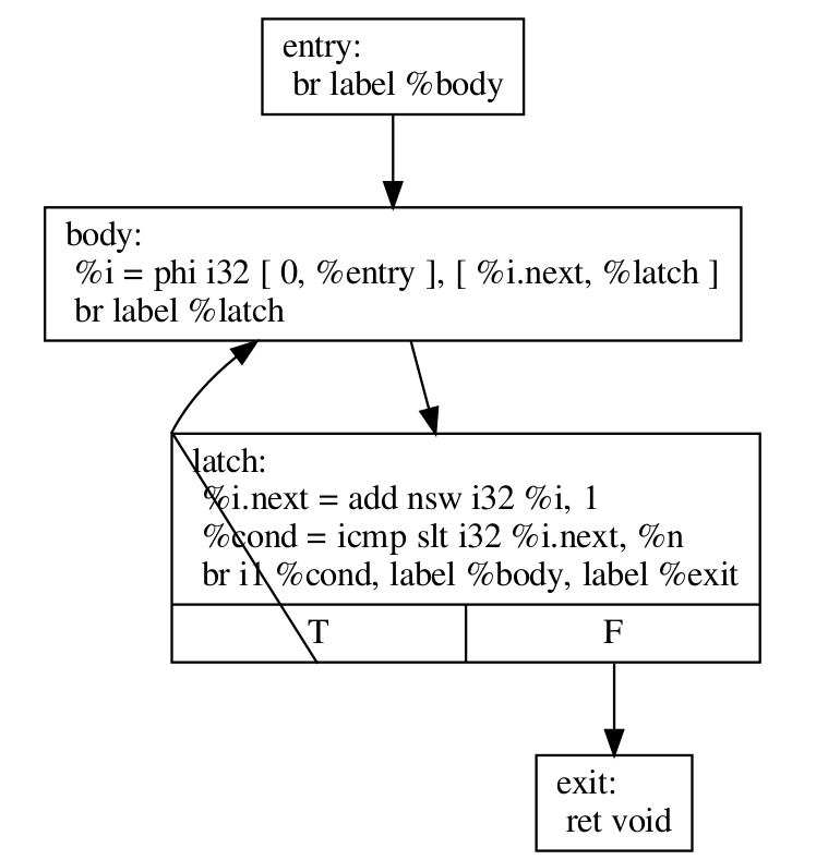
The following video segment provides a great visual walkthrough of how phi nodes enable loops.
2019 EuroLLVM Developers’ Meeting: V. Bridgers & F. Piovezan “LLVM IR Tutorial - Phis, GEPs ...”
This segment of the EuroLLVM IR Tutorial explains how to fix an iterative factorial implementation to be correct under SSA using phi instructions.
Watch the segment from the introduction of Phi to see how two phi nodes are used to correctly track the loop counter and the accumulating result in a loop.
Visualizing Control Flow: The CFG
The combination of basic blocks and the branches between them forms a directed graph called the Control Flow Graph (CFG). In a CFG, basic blocks are the nodes and the br instructions define the edges. Visualizing the CFG is an incredibly powerful way to understand a function's logic at a high level.
LLVM provides tools to do this automatically. For example, you can use opt -analyze -view-cfg your_ir_file.ll to generate and display a CFG.
Let's look at a more complex, real-world example.

By tracing the arrows and inspecting the br and phi instructions, you can reverse-engineer the entire logic of the binarySearch algorithm directly from the IR. This is a skill you will use constantly when analyzing bugs or understanding optimizer behavior.
Conclusion
In this lesson, you've learned to decode the logic of LLVM IR. You now understand the two fundamental instructions that give structure to programs: br to direct execution, and phi to merge data from different execution paths in an SSA-compliant way.
Key Takeaways:
- Terminators: Every basic block must end with a terminator instruction that transfers control, like
brorret. brInstruction: Comes in two forms: unconditional (br label) for simple jumps and conditional (br i1, label, label) forif-like decisions.phiInstruction: Solves the SSA merge problem by selecting a value based on the predecessor basic block. It is the key to representing variables whose values depend on the path taken.- Loops: Are constructed from conditional branches that jump backward and
phinodes that manage loop-carried variables (like induction variables). - Control Flow Graph (CFG): A visual representation of a function's logic, where basic blocks are nodes and branches are edges.
In our next lesson, we will explore metadata. While br and phi define a program's logic, metadata allows us to attach extra, non-logical information to the IR, such as source code line numbers for debugging or type information for runtime checks.