Introduction
Welcome to the final lesson in our Power Management module. Over the past few lessons, you have mastered the techniques for putting your STM32 microcontroller into various low-power modes—Sleep, Stop, and Standby—and waking it up using both external events and the internal Real-Time Clock (RTC). You've learned the theory behind why these modes save power.
Today, we transition from theory to empirical validation. Our learning outcome is to measure the MCU's current consumption in different operating and low-power modes using a multimeter. This is a fundamental skill for any embedded engineer, especially in the automotive and IoT sectors where battery life and power efficiency are paramount. You will physically see the impact of the code you've been writing and learn to quantify the power savings you've achieved.
1. The 'Why' and 'How' of Current Measurement
Before we begin, let's establish why this skill is so critical. Measuring current allows you to:
- Estimate Battery Life: For any battery-powered device, current draw is the most critical factor in determining its operational lifetime.
- Validate Datasheet Claims: Manufacturers provide typical current consumption values in their datasheets. Measuring them yourself confirms that your system is operating as expected.
- Debug Power Issues: Unusually high current draw can indicate a hardware fault or a software bug that prevents the MCU from entering a low-power state correctly.
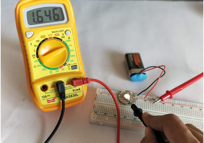
To measure current, the multimeter must be configured as an ammeter and placed in series with the component whose current you want to measure. This is different from measuring voltage, where the meter is placed in parallel. Placing the meter in series forces the current to flow through the meter, allowing it to be measured.
2. Setting Up the Measurement Rig for the Blue Pill
Unlike some development boards (like ST's Nucleo series) that have dedicated jumpers (often labeled IDD) to simplify current measurement, the STM32 Blue Pill board does not. We need to manually insert our multimeter into the board's power supply line.
The most reliable way to do this is to power the Blue Pill from your ST-Link programmer but intercept the 3.3V line with the multimeter.
The following article provides an excellent wiring guide for this exact setup.
This article from Mischianti's blog provides clear diagrams for setting up a power measurement test bench for the STM32F103 Blue Pill, which is exactly what we need.
Please read the section titled 'Wiring for our tests'. Focus on the first diagram, titled 'STM32: programming via ST-Link, Serial debug via FTDI, and Amperage check on breadboard'. This diagram shows precisely how to connect the ST-Link, Blue Pill, and multimeter. You can ignore the FTDI connection for now if you are not using it for serial printing.
To summarize the wiring connection:
- Set your digital multimeter to measure DC current (start with the mA range, e.g., 200mA).
- Connect the GND pin of the ST-Link directly to a GND pin on the Blue Pill.
- Connect the 3.3V pin of the ST-Link to the current input jack (often labeled
mAorA) of your multimeter using the red probe. - Connect the common jack (labeled
COM) of your multimeter to a 3.3V pin on the Blue Pill using the black probe. - Keep the ST-Link's
SWCLKandSWDIOpins connected to the Blue Pill as usual for programming and debugging.
This setup ensures that all power flowing from the ST-Link to the Blue Pill must first pass through your multimeter.
3. A Practical Demonstration
Before you take your own measurements, it's helpful to see what to expect. The following video demonstrates this process on a Nucleo board. While the hardware connection is simpler due to the IDD jumper, the effect on the multimeter reading is exactly what you are aiming to observe.
Sleep & Low Power Modes with STM32
This video from '1s and 0s' provides a great live demonstration of measuring current consumption as an STM32 board enters Sleep, Stop, and Standby modes. Pay attention to how the value on the multimeter drops significantly with each deeper sleep level.
Please watch the following segments: Sleep Mode (09:31 - 11:50): Observe the setup and the current drop from ~17-20mA in Run mode to ~5mA in Sleep mode. Stop Mode (25:16 - 26:30): Notice the much larger drop to ~1.5mA when the board enters Stop mode. Standby Mode (34:51 - 36:30): See the dramatic drop to the microampere (µA) range. The presenter has to change the multimeter's scale to even measure it.
4. Hands-On Experiment: Quantifying Power Savings
Now it's your turn. You will use a single program to cycle through the power modes and measure the current consumption of your Blue Pill board in each state.
Your Task:
-
Hardware Setup: Wire your ST-Link, Blue Pill, and multimeter as described in Section 2.
-
Project Setup: Create a new STM32CubeIDE project.
- Enable the
RCCHigh Speed Clock (HSE) to "Crystal/Ceramic Resonator". - Configure
PC13as aGPIO_Outputfor the onboard LED. - Configure
PA0(connected to the user button on many Blue Pill kits) as aGPIO_EXTIwith a falling edge trigger. In the NVIC settings, enable theEXTI line0 interrupt.
- Enable the
-
Firmware Implementation: In
main.c, we will use the external interrupt to cycle through power states./* Private variables */ volatile uint8_t power_mode = 0; // 0=Run, 1=Sleep, 2=Stop /* main.c */ int main(void) { // ... Initializations ... printf("System Running...\r\n"); while (1) { // This loop represents RUN mode. HAL_GPIO_TogglePin(GPIOC, GPIO_PIN_13); HAL_Delay(250); // Active work } } // EXTI Interrupt Callback void HAL_GPIO_EXTI_Callback(uint16_t GPIO_Pin) { if (GPIO_Pin == GPIO_PIN_0) { power_mode++; if (power_mode > 2) power_mode = 0; if (power_mode == 1) // Enter SLEEP { printf("Entering Sleep Mode. Press button to wake.\r\n"); HAL_Delay(100); // Allow printf to finish HAL_SuspendTick(); // Suspend SysTick to prevent it from waking the MCU HAL_PWR_EnterSLEEPMode(PWR_MAINREGULATOR_ON, PWR_SLEEPENTRY_WFI); // --- Execution resumes here on wake-up --- HAL_ResumeTick(); printf("Woke from Sleep. Now in Run mode.\r\n"); power_mode = 0; // Return to Run mode } else if (power_mode == 2) // Enter STOP { printf("Entering Stop Mode. Press button to wake.\r\n"); HAL_Delay(100); HAL_SuspendTick(); HAL_PWR_EnterSTOPMode(PWR_LOWPOWERREGULATOR_ON, PWR_STOPENTRY_WFI); // --- Execution resumes here on wake-up --- // After STOP mode, the system clock needs to be re-initialized SystemClock_Config(); HAL_ResumeTick(); printf("Woke from Stop. Now in Run mode.\r\n"); power_mode = 0; } // Note: We are not implementing Standby here as it requires a reset. // To measure Standby, you would create a separate program that enters // Standby mode immediately or after a short delay. } } -
Measure and Record:
- Flash the code and run it. The LED should be blinking. Measure and record the current. This is your Run mode current.
- Press the user button. The MCU will enter Sleep mode. Measure and record the current.
- Press the button again. The MCU wakes and returns to Run mode. Press it once more to enter Stop mode. Measure and record the current.
- For Standby Mode: Create a simplified program that enters Standby mode after a 5-second delay. You will likely need to switch your multimeter to the
µArange to get a reading.// Simplified main for Standby test int main(void) { // ... Init ... printf("Entering Standby in 5 seconds...\r\n"); HAL_Delay(5000); // Enter Standby mode HAL_PWR_EnterSTANDBYMode(); } - Compile your results into a table.
5. Analyzing Your Results
You should now have a table of measured current values. Compare them. You should see a clear trend:
Run > Sleep > Stop > Standby
Now, compare your values to the typical values for an STM32F103 listed in the resources.
STM32 Low Power Modes Explained
This article from ControllersTech and the Mischianti blog both provide tables with typical and measured current consumption values. Use them as a reference to validate your own findings.
Review the tables in the sections 'STM32 Power Consumption in Low Power Modes' and the final 'Comparison of STM32 Low-Power Modes'. Also, refer back to the 'Comparison table' at the end of the Mischianti article (Resource ID LINK).
An Important Real-World Observation:
You may have noticed that your measurements for Stop and Standby modes are much higher than the datasheet values (e.g., you might measure 1-2 mA instead of a few µA). Why?
The culprit is likely the power-on LED on your Blue Pill board. This LED and its resistor are connected directly across the 3.3V and GND lines. It consumes a relatively constant amount of current (~1-2 mA) regardless of what the MCU is doing. This parasitic draw completely masks the ultra-low current of the MCU in deep sleep modes.
To get a true measurement of the MCU's consumption, a professional engineer would desolder the power LED or its current-limiting resistor. This is an optional but highly instructive step if you feel comfortable with it.
Conclusion
Well done. You have successfully measured and validated the power consumption of your STM32 microcontroller, completing a critical hands-on exercise that bridges software configuration with hardware reality.
Key Takeaways:
- Current must be measured by placing a multimeter in series with the power supply.
- The hierarchy of power consumption is Run > Sleep > Stop > Standby, and you have now proven this with your own measurements.
- External components on a development board, like power LEDs, can significantly impact total current draw and must be accounted for in a power budget.
- This process of programming, measuring, and analyzing is the core workflow for power optimization in any embedded system.
Preview of the Next Lesson:
In this lesson, we focused on hardware-level power states. However, optimization doesn't stop there. How you write your code and how you configure your compiler also have a significant impact on performance and memory usage.
In our next lesson, we will begin exploring software-level optimization. The topic will be: "Optimize C code for size and speed using compiler flags and analyze the impact on the memory map." You will learn how to instruct the GCC compiler to build your firmware for maximum speed or minimum size, a crucial skill for resource-constrained systems.