Hello! Welcome back to our course on professional embedded systems engineering.
In the last lesson, we explored the theory of the ARM Cortex-M interrupt system, focusing on the NVIC, the vector table, and the concept of preemption. We established that an interrupt-driven approach is far more efficient than polling for handling asynchronous events.
Today, we transition from theory to practice. Our goal is to configure and implement an external interrupt (EXTI) for an edge-triggered event. We will take the button from our previous projects and re-wire our firmware to react to its press instantly, using a hardware interrupt instead of constantly checking its state in a loop. This is a fundamental skill for creating responsive, power-efficient embedded systems, which is especially critical in automotive applications where CPU resources must be managed carefully.
1. The EXTI Peripheral: Bridging the Physical World and the CPU
While the NVIC manages interrupts within the CPU core, another peripheral is needed to detect events from the outside world and signal the NVIC. This is the External Interrupt/Event Controller (EXTI). It acts as a configurable bridge between the GPIO pins and the NVIC.
Before we touch any registers, let's look at a block diagram of the EXTI peripheral to build a mental model of the process.
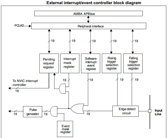
As you can see, an input signal from a pin goes through several stages:
- Edge Detect Circuit: This hardware block watches the pin's state and detects a change—a transition from low to high (rising edge) or high to low (falling edge).
- Trigger Selection Registers (RTSR/FTSR): We configure these registers to tell the edge detector which event we care about (rising, falling, or both).
- Interrupt Mask Register (IMR): This is a crucial gatekeeper. Even if a valid edge is detected, the interrupt signal will only be passed to the NVIC if the corresponding bit in this register is 'unmasked' (enabled).
- Pending Register (PR): When a valid, unmasked edge is detected, a bit is set in this register to flag that an interrupt has occurred. We must clear this flag in our code after handling the interrupt.
2. Mapping a GPIO Pin to an EXTI Line
A common source of confusion for beginners is the relationship between GPIO pins and EXTI lines. On the STM32F103, there are 16 EXTI lines (EXTI0 to EXTI15). However, there are many more GPIO pins. The system uses a multiplexer to connect only one pin to each EXTI line at a time.
For example, pins PA0, PB0, PC0, PD0... all share the EXTI0 line. We must explicitly configure which one is the active source for EXTI0. The same applies to line 1 (PA1, PB1, PC1...), line 2, and so on.
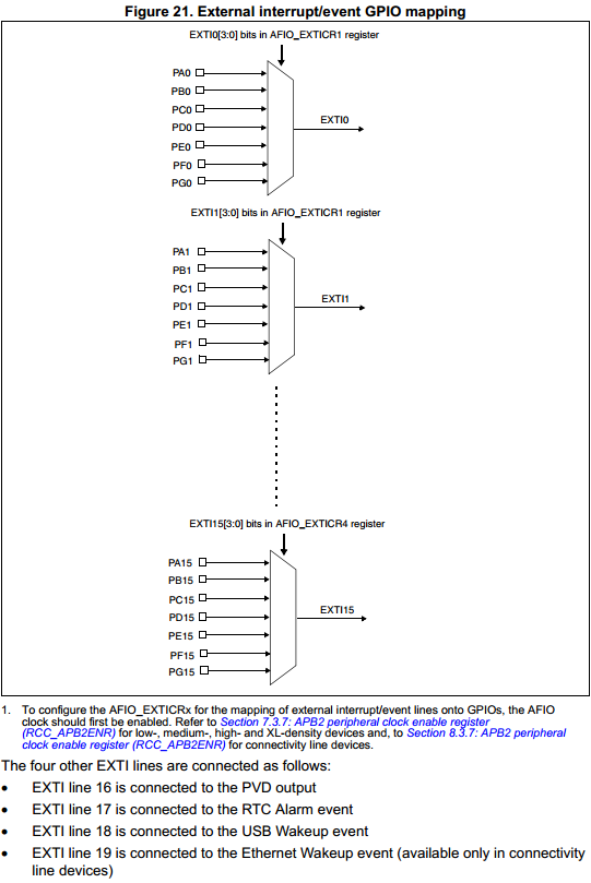
This selection is handled by the Alternate Function I/O (AFIO) peripheral. Before configuring the EXTI, we must tell the AFIO which pin we want to use.
3. The 5 Steps of EXTI Configuration
Configuring an external interrupt on the STM32F1 series using bare-metal register access involves a clear, five-step process. We will configure an interrupt on pin PB1 for a button press. Assume the button connects the pin to GND when pressed, and we use the internal pull-up resistor.
-
Enable Clocks (RCC):
- Enable the clock for the GPIO port being used (e.g., GPIOB).
- Enable the clock for the AFIO peripheral. Both are in the
RCC_APB2ENRregister.
-
Configure GPIO Pin:
- Set the pin (PB1) as a floating input or an input with pull-up/pull-down. Since our button connects to ground, we'll configure it as an input with an internal pull-up.
-
Configure AFIO Mapping:
- Write to the appropriate
AFIO_EXTICRregister to select the GPIO port for the EXTI line. For pinPB1(which usesEXTI1), we need to configure theEXTI1field inAFIO->EXTICR[0]to0001(for Port B).
- Write to the appropriate
-
Configure EXTI Registers:
- Unmask the interrupt in
EXTI->IMRfor the corresponding line (e.g., line 1). - Select the trigger edge in
EXTI->RTSRorEXTI->FTSR. For a button connected to GND with a pull-up, the voltage goes from HIGH to LOW when pressed, so we configure a falling edge trigger inEXTI->FTSR.
- Unmask the interrupt in
-
Configure NVIC:
- Enable the interrupt in the NVIC using the
NVIC_EnableIRQ()function provided by CMSIS. The correct IRQ number forEXTI1isEXTI1_IRQn. - Set the priority using
NVIC_SetPriority(), keeping in mind the concepts from our last lesson (lower number = higher priority).
- Enable the interrupt in the NVIC using the
4. Hands-On Implementation
Now, let's put these steps into code. The following video and article from ControllersTech provide a complete, register-level guide. They use PA1 in their example, but the process is identical for PB1.
First, let's watch the video to see the whole process in action.
#7. EXTernal Interrupt using Registers || STM32F4 || STM32F1 || NO HAL
This video from ControllersTech provides a step-by-step guide to configuring an external interrupt using bare-metal C on an STM32F1/F4. It clearly explains each register's role.
Watch the video from 01:53 to 11:46. This covers the entire configuration process: GPIO Configuration (01:53 - 04:37): Observe how the GPIO clock is enabled and the pin is set to input with pull-up. EXTI/AFIO Configuration (04:37 - 08:43): Pay close attention to how the AFIO clock is enabled and the EXTICR register is configured. Note the distinction made between F1 (AFIO) and F4 (SYSCFG) series. Edge Trigger and NVIC (08:43 - 11:46): See how the RTSR/FTSR registers are set and how the CMSIS functions NVIC_SetPriority and NVIC_EnableIRQ are used to finalize the setup.
For a textual reference you can follow while coding, the companion article is excellent.
STM32 External Interrupt via Registers
This article is the written version of the video, breaking down the configuration into clear, copy-pastable code snippets. Use this as your primary reference when writing your code.
Read the sections from '1. Enable the SYSCFG/AFIO Bit' through '5. Set the Interrupt Priority and Enable the Interrupt'. Compare the code for the F1 series with the 5 steps we outlined above.
5. Writing the Interrupt Service Routine (ISR)
When the configured event (a falling edge on PB1) occurs, the CPU automatically pauses the main loop, saves its context, and jumps to a specific function called the Interrupt Service Routine (ISR). The name of this function is predefined in the startup file. For EXTI1, the ISR is named EXTI1_IRQHandler.
Inside the ISR, you perform the action you need, for example, toggling an LED. However, there is one absolutely critical step you must perform.
You must clear the interrupt's pending flag.
In the EXTI peripheral, when an interrupt is triggered, the corresponding bit in the Pending Register (EXTI->PR) is set by hardware. This is the bit that tells the NVIC there's a pending interrupt. If you do not clear this bit in your ISR, the NVIC will think the interrupt is still pending as soon as the ISR finishes. This will cause the CPU to get stuck in a loop, constantly re-entering the ISR and never returning to your main code.
To clear the flag, you write a '1' to the corresponding bit in EXTI->PR.
Let's see how this is done in the video, which also includes a fantastic real-world debugging example of what happens when you forget to clear the flag correctly.
#7. EXTernal Interrupt using Registers || STM32F4 || STM32F1 || NO HAL
This final segment of the video demonstrates how to write the ISR and debug a common issue related to the pending flag.
Watch from 11:23 to 17:12. ISR Handler (11:23 - 13:32): See how the EXTI_PR register is checked and, importantly, how the pending bit is cleared. Debugging (15:10 - 17:12): This is an invaluable section. The author makes a mistake and the program fails. Watch carefully how they diagnose and fix the issue related to clearing the pending bit. This is a lesson every embedded engineer learns early in their career.
Your Turn: Putting It All Together
Now it's your turn to implement this. Create a new project in STM32CubeIDE.
- Create a function
void button_interrupt_config(void). - Inside this function, implement the 5 configuration steps for pin PB1 using direct register access (
RCC->...,GPIOB->...,AFIO->...,EXTI->...,NVIC_...). - Also configure the onboard LED pin (PC13) as a push-pull output.
- Implement the
EXTI1_IRQHandler(void)function. Inside it, toggle the LED on PC13 and immediately clear the pending flag for EXTI line 1. - In
main(), call your configuration function, and then have an emptywhile(1)loop.
Compile, flash, and run the code. When you press the button, the LED should toggle. The CPU is now free to do other tasks (or sit idle in the empty while loop) and will only spend cycles on the button when it's actually pressed.
Conclusion
Congratulations! You have successfully implemented a hardware interrupt, a cornerstone of modern embedded programming. You've moved beyond inefficient polling and created a truly event-driven system.
Key Takeaways:
- The EXTI peripheral detects edge transitions on GPIO pins and signals the NVIC.
- The AFIO peripheral is used on STM32F1 devices to map a specific GPIO pin (e.g., PB1) to its corresponding EXTI line (e.g., EXTI1).
- Configuration is a 5-step process: Enable clocks (GPIO, AFIO), configure GPIO mode, configure AFIO mapping, configure EXTI (mask, trigger), and configure NVIC (enable, priority).
- Inside the ISR (e.g.,
EXTI1_IRQHandler), it is absolutely mandatory to clear the pending flag in theEXTI->PRregister to prevent the CPU from getting stuck in an interrupt loop.
Preview of the Next Lesson:
Our current interrupt toggles an LED, but it doesn't handle the "bouncing" of the mechanical button. If you press the button slowly, you might see the LED flicker. In the next lesson, we will focus on writing a safe and efficient ISR, including a robust software debouncing algorithm that works correctly within an interrupt context. We will then assemble all the pieces from this module into a final project: controlling an LED's state using a debounced button press via an interrupt.