Hello! Welcome to the next lesson in your journey to becoming a professional embedded systems engineer.
In our last session, we built a non-blocking debouncing algorithm. While effective, our main loop was still constantly polling the button's GPIO pin, consuming CPU cycles to repeatedly ask, "Are you pressed yet?". This is inefficient. In professional systems, especially in automotive applications where every microsecond and microamp counts, we need a better way. We need the microcontroller to react to events, not constantly look for them.
This lesson introduces the hardware mechanism that makes this possible: interrupts. Our learning outcome is to describe the ARM Cortex-M NVIC architecture and interrupt preemption. We will explore the theory behind how the CPU can suspend its current task to handle an important event—like a CAN message arriving or a button press—and then seamlessly resume its work. Understanding this is non-negotiable for building the robust, responsive, and power-efficient firmware required in modern vehicles.
1. From Polling to Interrupts: A Paradigm Shift
Imagine you're waiting for an important email. The polling approach is like hitting the "refresh" button in your inbox every five seconds. It works, but it's distracting and wastes your time. The interrupt-driven approach is like enabling notifications; you can focus on other work, and your computer will alert you the moment the email arrives.
This is precisely the difference between the polling-based debouncer we built and an interrupt-driven system.
To start, let's watch a short video that introduces this core concept and its benefits.
This video from the 'Embedded Systems and Deep Learning' channel provides an excellent analogy to explain why interrupts are more efficient than polling.
Watch the first part of the video from the beginning until 02:37. Focus on the comparison between the polling and interrupt methods for handling a button press.
As the video explains, an interrupt is a hardware signal from a peripheral (like a GPIO pin, timer, or UART) to the CPU, signaling that an event needs immediate attention.
2. The NVIC: The Conductor of the Interrupt Orchestra
On ARM Cortex-M microcontrollers, all interrupts are managed by a sophisticated piece of hardware called the Nested Vectored Interrupt Controller (NVIC). The name itself tells us a lot about its function:
- Nested: It can handle interrupts that occur while another interrupt is already being serviced. This is achieved by assigning priorities, allowing a high-priority event (like an airbag sensor) to preempt a low-priority one (like a touchscreen press).
- Vectored: It uses a special lookup table, the Interrupt Vector Table, to quickly find the correct code to run for each specific interrupt.
Let's get a more formal introduction to the NVIC.
Interrupts on Cortex M - NVIC (demonstrated on STM32) | VIDEO 34
This video by Matej Blagšič introduces the NVIC and its key terminology.
Watch from 00:37 to 02:08. Pay attention to the definition of the NVIC and the term Interrupt Service Routine (ISR), which is the function that executes when an interrupt occurs.
The Interrupt Vector Table
How does the CPU know which ISR to run when, for example, the UART peripheral signals that it has received a byte? The answer lies in the Interrupt Vector Table.
Think of this table as a directory or an array of function pointers stored at a specific, known location in memory (starting at address 0x00000004). Each interrupt source in the microcontroller is assigned a unique Interrupt Request (IRQ) number. This number serves as an index into the vector table. When an interrupt occurs:
- The NVIC receives the interrupt signal and its IRQ number.
- The CPU uses this number to look up the corresponding entry in the vector table.
- That entry contains the memory address of the ISR to execute.
- The CPU then "jumps" to that address and starts running the ISR.
This process is extremely fast and handled entirely by hardware, ensuring a low-latency response.
The 'Embedded Systems and Deep Learning' video gives a very clear explanation of how the vector table works.
Watch the segment from 07:01 to 12:30. This part explains the structure of the vector table and how the IRQ number is used to find the correct ISR address.
3. The Interrupt Mechanism: Context Switching with the Stack
When an interrupt occurs, the CPU must suspend its main program, execute the ISR, and then return to the main program as if nothing happened. To achieve this, it must save its current "context"—the state of its internal registers, including the Program Counter (which holds the address of the next instruction to execute).
Given your background, you're familiar with how the stack is used during function calls to store return addresses and local variables. The interrupt mechanism is similar but even more powerful because it's automated in hardware.
When an interrupt is triggered:
- Hardware Stacking: The CPU automatically pushes the contents of several core registers (like the Program Counter, Link Register, and general-purpose registers) onto the stack. This creates a snapshot of the system's state.
- ISR Execution: The CPU executes the ISR. Because the context is saved, the ISR can be a standard C function and can freely use the CPU registers without corrupting the main program's state.
- Hardware Unstacking: When the ISR finishes, a special instruction signals the CPU to pop the saved values from the stack back into the registers.
- Resuming Execution: The Program Counter is restored to its original value, and the main program continues executing from the exact point where it was interrupted.
This automatic context switching is a cornerstone of the Cortex-M architecture, making interrupt handling both fast and easy to program.
Interrupts on Cortex M - NVIC (demonstrated on STM32) | VIDEO 34
To see this process in detail, we'll return to Matej Blagšič's video. He provides an excellent visual analogy, first explaining stack frames for regular function calls and then extending the concept to interrupts.
Watch the detailed explanation from 05:04 to 12:04. This is a critical section for deeply understanding the underlying mechanics of what happens during an interrupt.
4. Interrupt Preemption: Handling Events by Priority
In any complex system, not all events are equally urgent. In an automotive context, a signal from the anti-lock braking system (ABS) is infinitely more critical than a signal from the volume knob. The NVIC allows us to manage this through interrupt preemption.
- Each interrupt is assigned a priority level. Crucially, a lower number means a higher priority. Priority 0 is the highest, priority 15 is lower, and so on.
- When an ISR is executing, it can only be interrupted (preempted) by an incoming interrupt that has a strictly higher priority.
- If an interrupt arrives that has a lower or equal priority, it is marked as "pending" and will only be serviced after the current, higher-priority ISR completes.
- If multiple interrupts are pending at the same priority level, the one with the lower exception number (its position in the vector table) is serviced first.

The following video segment illustrates this process beautifully.
This final clip from the 'Embedded Systems and Deep Learning' video explains how the NVIC handles multiple interrupts, demonstrating both preemption and the tail-chaining optimization.
Watch from 16:31 to 20:41. Focus on the two scenarios presented: when a higher-urgency interrupt arrives (preemption) and when a lower-urgency interrupt arrives (tail-chaining).
5. Professional Concepts: Priority Grouping and Optimizations
For professional firmware development, especially when working with a Real-Time Operating System (RTOS), you need a finer degree of control over preemption. The NVIC provides this through priority grouping.
The priority bits for each interrupt (on the STM32F1, there are 4 bits, giving 16 priority levels) can be split into two fields:
- Preemption Priority: This determines whether an interrupt can preempt another.
- Sub-priority: This is a tie-breaker. If two pending interrupts have the same preemption priority, the one with the higher sub-priority (lower number) will be serviced first.
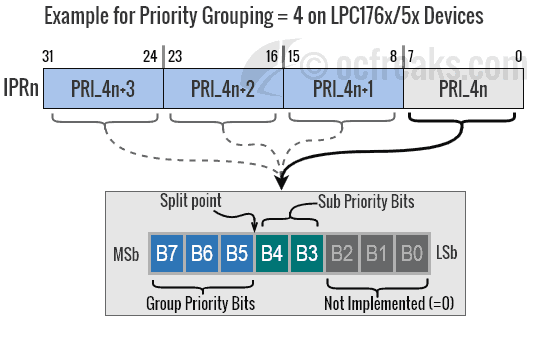
To deepen your understanding of the NVIC architecture and these advanced concepts, the following article from Memfault is an industry-standard resource.
A Practical guide to ARM Cortex-M Exception Handling
This article, 'A Practical guide to ARM Cortex-M Exception Handling,' provides a comprehensive, professional-level deep dive into the topics we've discussed.
Please read the following sections: ARM Exception Model Overview: This section clearly defines key terminology like exception states (Pending, Active, Inactive) and distinguishes between built-in system exceptions and external interrupts. Advanced Exception Topics: Read about Tail-Chaining and Late-arriving Preemption. These are hardware optimizations that reduce interrupt latency, a critical factor in high-performance systems. Also, read the section on Execution Priority & Priority Boosting which introduces the special registers (PRIMASK, BASEPRI) used to disable interrupts temporarily, forming what is known as a 'critical section'.
Conclusion
Today, we've pulled back the curtain on one of the most powerful features of the ARM Cortex-M architecture. You've learned how interrupts provide an efficient, event-driven alternative to polling and how the NVIC orchestrates the entire process.
Key Takeaways:
- An interrupt is a hardware signal that suspends the main program to execute a special function called an Interrupt Service Routine (ISR).
- The Nested Vectored Interrupt Controller (NVIC) manages all interrupts, using the Interrupt Vector Table to quickly locate the correct ISR.
- The CPU hardware automatically saves and restores the program's context (register state) on the stack, allowing for seamless transitions between the main code and an ISR.
- Preemption, based on configurable priority levels, allows critical events to be handled immediately, even if a less important task is already running.
- Advanced features like priority grouping and hardware optimizations like tail-chaining provide the performance and control needed for demanding real-time applications.
Preview of the Next Lesson:
We have covered the theory of what an interrupt is and why it's useful. In our next lesson, we will put this knowledge into practice. You will learn how to configure and implement an external interrupt (EXTI) to handle our button press, finally freeing the CPU from the inefficient task of polling and building a truly event-driven system.