Hello! Welcome to the next lesson in our module on Data Acquisition and DMA.
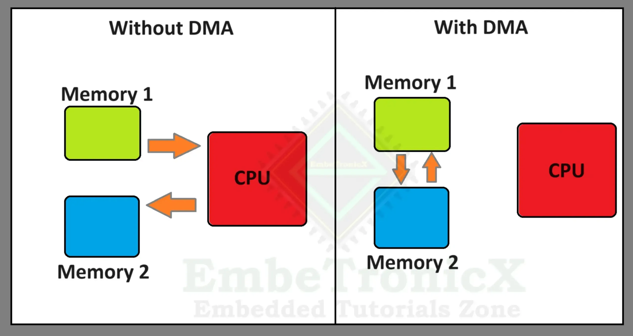
In the previous lesson, we established the "what" and "why" of the Direct Memory Access controller. We learned that it's a specialized co-processor that acts as a second bus master, designed to move data efficiently without CPU intervention. This frees up the CPU, reduces power consumption, and enables high-throughput data handling, which is critical in complex automotive systems.
Today, we transition from theory to practice. Your learning outcome for this lesson is to configure a DMA channel for a basic memory-to-memory transfer. We will start with this fundamental operation because it allows us to focus entirely on the DMA controller's configuration and behavior, without the added complexity of a peripheral's timing and triggers. This is the "Hello, World!" of DMA.
1. Anatomy of a DMA Transfer
Before we open the IDE, let's solidify the core parameters you'll be configuring. A memory-to-memory (M2M) transfer is conceptually simple: you're telling the DMA to copy a block of data from one location in memory (a source buffer) to another (a destination buffer).
To do this, the DMA controller needs to be programmed with a few key pieces of information, which map directly to its internal registers:
- Source Address: The starting memory address of the data you want to copy.
- Destination Address: The starting memory address where the data should be placed.
- Transfer Count: The total number of data items to transfer.
- Transfer Direction: In this case, Memory-to-Memory.
- Data Width: The size of each data item (e.g., 8-bit byte, 16-bit half-word, or 32-bit word).
- Address Increment: Whether to automatically increment the source and destination addresses after each item is transferred. For copying a buffer, you'll want to increment both.
The following video provides a practical look at these configuration parameters and how they are represented in the DMA registers and HAL library.
DMA on STM32 HAL with 2 example projects | VIDEO 36
The video 'DMA on STM32 HAL' by Matej Blagšič gives an excellent overview of the parameters that define a DMA transfer. It's for an F4 series MCU, but the concepts of pointers, data width, and incrementation are universal.
Watch the segment from 10:56 to 18:22. Focus on understanding the four key configuration parameters discussed: Source and Destination Pointers Data Width (byte, half-word, word) Pointer Incrementation Transfer Flow (Normal vs. Circular mode)
As you saw, a DMA transfer is a highly configurable operation. For our M2M copy, we will use Normal mode with pointer incrementation enabled for both the source and destination.
2. Hands-On Lab: Your First DMA Transfer
It's time to put this into practice. We will use STM32CubeIDE to configure the DMA for a memory-to-memory transfer, write the necessary code using the HAL library, and verify the result with the debugger.
This tutorial provides a clear, step-by-step guide. While it uses an STM32F7, the process in CubeIDE and the HAL function calls are nearly identical for your STM32F103.
STM32 DMA Tutorial - Part 1 (Memory to Memory Transfer)
The article 'STM32 DMA Tutorial - Part 1 (Memory to Memory Transfer)' from Embetronicx will be our main guide for this lab. It walks through the entire process from project creation to verification.
Read through the sections 'Memory to Memory data transfer using DMA in STM32', 'Source Code', and 'Demo'. We will follow these steps together. Don't worry about the specific MCU (STM32F7) or DMA controller (DMA2) mentioned; the principles are the same.
Let's walk through this process.
Step 1: Project Configuration in STM32CubeIDE
- Create a new STM32 project for your
STM32F103C8T6board. - In the
Pinout & Configurationtab, go to System Core > DMA. - Click the Add button. A new DMA request line will appear (e.g.,
DMA1 Channel 1). - In the configuration pane for this new channel, set the Direction to Memory to Memory.
- Set the Mode to Normal.
- Ensure Increment Address is enabled for both
PeripheralandMemory. For an M2M transfer, "Peripheral" simply refers to the source address, and "Memory" refers to the destination. - Set the
PeripheralandMemoryData Width to Byte. We will be copying a character array. - Now, go to the NVIC Settings tab for the DMA configuration (or select System Core > NVIC) and enable the interrupt for the DMA channel you just configured (e.g.,
DMA1 channel 1 global interrupt). This is crucial, as it allows the DMA controller to signal the CPU upon completion.

- Save the
.iocfile to generate the initialization code.
Step 2: Writing the Application Code
Navigate to Core/Src/main.c. We'll add the code to define our data buffers and start the DMA transfer.
-
In the
/* USER CODE BEGIN PV */section (for private variables), define your source and destination buffers./* USER CODE BEGIN PV */ uint8_t source_buffer[] = "Hello DMA! This is a test string."; uint8_t destination_buffer[100] = {0}; // Initialize with zeros volatile uint8_t transfer_complete_flag = 0; // A flag to signal completion /* USER CODE END PV */The
volatilekeyword is important fortransfer_complete_flagbecause it will be modified by an interrupt and checked in the main loop. This prevents the compiler from optimizing away the checks. -
The Embetronicx tutorial registers a custom callback function. A more standard HAL approach is to implement the predefined "weak" callback function. Add the following function in the
/* USER CODE BEGIN 4 */section. This function will be automatically called by the HAL driver when the DMA transfer completes./* USER CODE BEGIN 4 */ void HAL_DMA_TxCpltCallback(DMA_HandleTypeDef *hdma) { // This function is called when the DMA transfer is complete. // Set our flag to signal the main loop. transfer_complete_flag = 1; } /* USER CODE END 4 */ -
In
main(), inside the/* USER CODE BEGIN 2 */section, add the single line of code that starts the DMA transfer./* USER CODE BEGIN 2 */ // Start the DMA transfer with interrupts enabled if (HAL_DMA_Start_IT(&hdma_memtomem_dma1_channel1, (uint32_t)source_buffer, (uint32_t)destination_buffer, sizeof(source_buffer)) != HAL_OK) { // Transfer Error Error_Handler(); } // The CPU is now free to do other things while the DMA works. // For this demo, we'll just wait for the flag to be set. while (transfer_complete_flag == 0) { // Do nothing, or do other work... } // At this point, the transfer is complete. We can add a NOP // to place a breakpoint and verify the destination buffer. __NOP(); /* USER CODE END 2 */Note: Your DMA handle might be named differently (e.g.,
hdma_dma1_channel1). Use the one generated by CubeIDE in yourmain.cfile.Let's break down
HAL_DMA_Start_IT():&hdma_memtomem_dma1_channel1: A pointer to the DMA handle structure that contains all our configuration.(uint32_t)source_buffer: The source address. We cast the array name to a 32-bit integer pointer.(uint32_t)destination_buffer: The destination address.sizeof(source_buffer): The number of bytes to transfer.
Step 3: Verification with the Debugger
This is the most important part: proving that the transfer worked.
- Build the project and start a Debug Session.
- Open the "Expressions" view (Window > Show View > Expressions).
- Add
source_bufferanddestination_bufferto this view. You will be able to see their contents live. - Initially,
destination_bufferwill be all zeros. - Place a breakpoint on the
__NOP();line in yourmainfunction. - Resume the execution (
F8). The program will run, theHAL_DMA_Start_ITfunction will execute, and the CPU will wait in thewhileloop. The DMA controller will perform the transfer in the background. - Once the transfer is complete, the DMA interrupt will fire, your
HAL_DMA_TxCpltCallbackwill execute (settingtransfer_complete_flag = 1), thewhileloop will terminate, and execution will pause at your breakpoint. - Now, inspect the
destination_bufferin the Expressions view. You should see that it has been perfectly populated with the contents ofsource_buffer.
You have just successfully performed a data transfer without writing a single for loop or using any CPU cycles for the copy operation itself!
Conclusion
Congratulations on completing your first hands-on DMA lab! By configuring a memory-to-memory transfer, you have mastered the fundamental mechanics of the DMA controller in a controlled environment.
Key Takeaways:
- A memory-to-memory (M2M) transfer is an ideal starting point for learning DMA as it isolates the DMA controller from peripheral-specific logic.
- Configuration in CubeIDE involves setting the direction, mode, address increment behavior, and data width for a DMA channel.
- Enabling the DMA channel's interrupt in the NVIC is essential for signaling completion.
- The
HAL_DMA_Start_IT()function is used to initiate an interrupt-driven DMA transfer. - The
HAL_DMA_TxCpltCallback()function provides a clean, standard way to execute code immediately after a DMA transfer is finished.
Preview of the Next Lesson:
Now that you can configure the DMA for a basic transfer, it's time to connect it to a peripheral and solve a real problem. In the next lesson, we will configure DMA for peripheral-to-memory transfer to read ADC results without CPU intervention. This will directly address the CPU bottleneck we identified earlier and demonstrate the true power of DMA in data acquisition systems.