Hello! Welcome back to our module on Data Acquisition and DMA.
In the last lesson, you successfully configured the DMA to transfer a single ADC conversion result into memory. This was a crucial first step in offloading work from the CPU. We used the DMA in Normal mode, which is perfect for one-shot measurements.
Today, we're building a system that's far more powerful and common in real-world applications, especially in automotive systems where constant monitoring is key. Your learning outcome is to set up the ADC in scan mode with DMA to continuously acquire data from multiple channels. This will allow you to monitor several sensors simultaneously, in a continuous loop, with virtually zero CPU intervention. This is the foundation for everything from engine management to battery monitoring systems.
1. The Core Concepts: Scan Mode and Circular Mode
To achieve continuous multi-channel acquisition, we need to combine two new features: ADC Scan Mode and DMA Circular Mode.
ADC Scan Conversion Mode
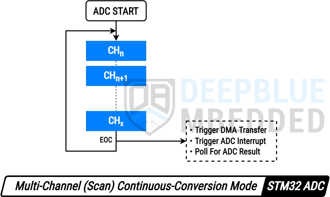
Instead of converting just one channel, Scan Mode tells the ADC to automatically convert a whole sequence of pre-configured channels (e.g., Channel 0, then Channel 1, then Channel 5) after a single start trigger. The order of conversion is determined by a setting called Rank.
ADC Continuous Conversion Mode
When this mode is enabled, the ADC will automatically restart the entire scan sequence as soon as the last channel in the sequence is converted. It doesn't wait for another trigger.
DMA Circular Mode
In the previous lesson, we used Normal mode, where the DMA stops after transferring the requested number of data items. In Circular mode, the DMA treats the destination memory buffer like a ring. After it writes the last element, it automatically wraps around and starts writing to the first element again.
When you combine these three, you create a self-sustaining data pipeline:
- The ADC starts, scans all channels, and places the results in its data register.
- The DMA, triggered by the ADC, copies each result to your memory buffer.
- Because the ADC is in continuous mode, it immediately starts the scan sequence again.
- Because the DMA is in circular mode, it continues to copy the new results, overwriting the old ones in the buffer.
The CPU's only job is to start this process once. Afterward, the adc_values array in your code becomes a live, continuously updated snapshot of all your sensor readings.
This article from ControllersTech provides an excellent overview comparing the different DMA modes.
STM32 ADC Multiple Channels using Circular DMA
To solidify your understanding, please read the introductory sections of the article 'STM32 ADC Multiple Channels using Circular DMA'.
Read the sections 'What is Multi-Channel DMA Normal Mode?' and 'ADC Multi-Channel Modes Comparison'. Pay close attention to the table, which clearly contrasts the DMA Normal, DMA Circular, and Interrupt-based methods. This will help you understand why we are choosing circular mode today.
2. Hands-On Lab: Continuous Multi-Channel Acquisition
Let's implement this. We will configure the ADC to continuously read two external channels and store the results in an array using DMA circular mode.
Step 1: Project Configuration in STM32CubeIDE
- Open your project from the last lesson. Go to the
.iocfile for Pinout & Configuration. - Go to Analog > ADC1.
- Ensure you have at least two channels enabled, for example,
IN0(on pin PA0) andIN1(on pin PA1). You can connect potentiometers to these pins to simulate sensor inputs. - In the ADC1 Parameter Settings pane, configure the following:
- Under
ADC_Regular_ConversionMode:- Scan Conversion Mode: Set to
Enabled. - Continuous Conversion Mode: Set to
Enabled. This is critical for the "fire-and-forget" operation. - Number Of Conversions: Set to
2(or the number of channels you enabled).
- Scan Conversion Mode: Set to
- You will now see
Ranksettings appear. Configure them:- Rank 1: Channel
Channel 0, Sampling Time can be left at a default like1.5 Cycles. - Rank 2: Channel
Channel 1, same Sampling Time.
- Rank 1: Channel
- Under
- Now, go to the DMA Settings tab. If you have a DMA channel for ADC1 from the last lesson, select it. If not, add one.
- Verify or set these crucial DMA parameters:
- Direction:
Peripheral To Memory. - Mode:
Circular. This is the key change from our previous lesson. - Increment Address: Check
Memory, uncheckPeripheral. - Data Width:
Half Wordfor both Peripheral and Memory.
- Direction:
The following video walks through this exact configuration. It also shows the specific settings for your STM32F103C8 board.
STM32 ADC Tutorial (Part4): How to read Multiple Channels using DMA in Circular Mode
The video 'STM32 ADC Tutorial (Part4)' by ControllersTech demonstrates the CubeMX setup for multi-channel ADC with circular DMA. We'll watch the relevant parts for configuration.
Watch the segment from 00:58 to 02:52. The first part shows the general setup, and the second part (starting at 02:18) specifically shows the simpler configuration required for the STM32F103C8, which is your target device. Focus on enabling 'Scan Conversion Mode', 'Continuous Conversion Mode', and DMA 'Circular' mode.
- Save the
.iocfile to generate the updated code.
Step 2: Writing the Application Code
The application code becomes remarkably simple.
-
In
Core/Src/main.c, navigate to the private variables section/* USER CODE BEGIN PV */. Define an array to hold the results from your ADC channels. Since it will be accessed by the DMA hardware, it's good practice to declare itvolatile./* USER CODE BEGIN PV */ volatile uint16_t adc_values[2]; // Buffer for 2 ADC channels /* USER CODE END PV */ -
Now, find the
main()function. We need to start the ADC/DMA process once, before the main loop.int main(void) { /* MCU Configuration--------------------------------------------------------*/ /* Reset of all peripherals, Initializes the Flash interface and the Systick. */ HAL_Init(); /* Configure the system clock */ SystemClock_Config(); /* Initialize all configured peripherals */ MX_GPIO_Init(); MX_DMA_Init(); MX_ADC1_Init(); /* USER CODE BEGIN 2 */ // Start the ADC in DMA mode. This is a one-time call. HAL_ADC_Start_DMA(&hadc1, (uint32_t*)adc_values, 2); /* USER CODE END 2 */ /* Infinite loop */ /* USER CODE BEGIN WHILE */ while (1) { // The CPU is now completely free. // The 'adc_values' array is being updated in the background. // We could do other tasks here, like process the data, // run a control loop, or handle communication. // For demonstration, we'll just add a delay. HAL_Delay(100); /* USER CODE END WHILE */ /* USER CODE BEGIN 3 */ } /* USER CODE END 3 */ }Notice the elegance here. There are no flags, no callbacks, and no
HAL_ADC_Start_DMAcall inside thewhile(1)loop. The hardware is now running an autonomous data acquisition engine.
Step 3: Verification with the Debugger
The best way to see this in action is with the live debugger.
- Build the project and start a Debug Session.
- Open the Expressions view (Window > Show View > Expressions).
- Click "Add new expression" and enter
adc_values. - In the toolbar, find and enable "Continuous Refresh". This tells the debugger to constantly poll the values from the microcontroller.
- Resume (
F8) the program execution. - You should now see the
adc_valuesarray in the Expressions view. If you expand it, you will see two elements. As you turn the potentiometers connected to PA0 and PA1, you will see the corresponding values in the array change in real-time.
The debugging section of the video you watched earlier demonstrates this exact process.
STM32 ADC Tutorial (Part4): How to read Multiple Channels using DMA in Circular Mode
Let's re-watch a small portion of the video to see how to verify our results in the debugger.
Watch the segment from 03:10 to 04:27. Observe how the values in the live expression window update continuously as the potentiometers are adjusted. This is what you should aim to replicate.
3. A More Robust Approach: Timer-Triggered Scans
The Continuous Conversion Mode is simple and effective. However, in professional applications requiring precise timing (like control systems or signal processing), it's better to trigger ADC scans with a hardware timer. This ensures that your samples are taken at an exact, deterministic rate (e.g., precisely every 10ms).
You would configure a timer (like TIM3) to generate a trigger output (TRGO) on its update event, and then set the ADC's external trigger source to that timer.

While we won't implement this today to keep the lesson focused, the article "STM32 Internal Temperature Sensor Reading" provides a complete guide on this timer-triggered architecture. It's an excellent resource for future reference.
Conclusion
Congratulations! You have now built a truly efficient, multi-channel data acquisition system. By using ADC Scan Mode with DMA Circular Mode, you've created a fire-and-forget data pipeline that continuously updates a memory buffer with sensor readings, leaving the CPU almost entirely free to perform other tasks.
Key Takeaways:
- ADC Scan Mode converts a ranked sequence of channels with a single trigger.
- DMA Circular Mode makes the destination buffer a ring, allowing for continuous data overwriting.
- Combining ADC Continuous Conversion with these two modes creates an autonomous data acquisition engine.
- The
HAL_ADC_Start_DMA()function is called only once to kick off this self-sustaining process. - The debugger's Live Expressions view is the perfect tool for observing the continuously updated data buffer.
Preview of the Next Lesson:
Our adc_values buffer is now "live," but how do we safely process this data in our main application without reading it while the DMA is in the middle of an update (a "torn read")? In our next lesson, we will explore using DMA interrupts (Transfer Complete and Half-Transfer) to create a robust double-buffering scheme. This is the standard professional technique for processing continuous streams of data safely and efficiently.