Introduction
Welcome back! In our last module, you successfully built and tested a complete two-node CAN network. This was a significant achievement in systems integration, where you made separate hardware components communicate reliably. Throughout that process, we relied on the STM32CubeIDE toolchain to compile our code and flash it to the boards, without diving into how the final program was organized inside the microcontroller's memory.
This lesson begins a new module focused on the low-level foundations of system control. We'll peel back the curtain on the "magic" of the build process. Our goal is to analyze a linker script to identify memory sections like .text, .data, .bss, heap, and stack.
Understanding the linker script is a rite of passage for an embedded engineer. It is the blueprint that tells the linker tool how to arrange your code and variables into the physical Flash and RAM of the microcontroller. Mastering this is essential for building complex systems with bootloaders, optimizing memory usage, and debugging some of the most challenging memory corruption bugs.
1. From Source Code to Executable: The Role of the Linker
Before we can analyze a linker script, let's clarify its role in the build process. When you click "Build" in your IDE, two key steps happen:
-
Compilation: The compiler (like
arm-none-eabi-gcc) takes each of your.csource files and translates it into a corresponding object file (e.g.,main.c->main.o). These object files contain machine code but have unresolved references. For example,main.odoesn't yet know the final memory address of a function it calls fromcan_driver.c. -
Linking: The linker (like
ld) takes all the object files, along with pre-compiled libraries, and merges them into a single executable file (e.g.,my_project.elf). The linker's job is to:- Resolve Symbols: Find the final address for every function and variable.
- Arrange Sections: Place all the code and data into a final memory layout according to a set of rules.
The linker script is that set of rules—a text file that acts as a blueprint for the final memory layout of your program.
Demystifying Firmware Linker Scripts
To start, let's get a solid conceptual overview. This article from the Memfault blog provides an excellent primer on what linking is and why it's so important in firmware development.
Please read the introduction and the sections titled "Brief Primer on Linking" and "Anatomy of a Linker Script". This will provide the context for the more detailed syntax we'll cover next.
2. The Anatomy of a Linker Script
As you just read, a linker script has two primary commands that define the memory map: MEMORY and SECTIONS.
The MEMORY Command
This command describes the physical memory regions available on the target microcontroller. You are essentially telling the linker, "Here is the hardware you have to work with."
For your STM32F103C8T6 "Blue Pill" board, the two most important regions are:
- FLASH: Starts at address
0x08000000, has a size of 64KB. It is read-only and executable (rx). This is where your program code is permanently stored. - SRAM: Starts at address
0x20000000, has a size of 20KB. It is readable, writable, and executable (rwx). This is volatile memory where your variables live and the stack operates during runtime.
Bare metal embedded lecture-4: Writing linker scripts and section placement
This video from Fastbit Embedded Brain Academy provides a professional walkthrough of the GNU linker command language. Let's watch the segment that explains the MEMORY command.
Watch from 04:19 to 12:21. The instructor explains how to use the MEMORY command to define memory regions, including their origin, length, and attributes (r, w, x). The example uses an STM32F4, but the concepts are identical for your STM32F1.
A typical MEMORY block for your STM32F103C8T6 would look like this:
MEMORY
{
  FLASH (rx) : ORIGIN = 0x08000000, LENGTH = 64K
  RAM (rwx)  : ORIGIN = 0x20000000, LENGTH = 20K
}
The SECTIONS Command and Program Memory Layout
The SECTIONS command is the core of the linker script. It instructs the linker on how to take the various sections from the input object files (.o files) and arrange them into the memory regions defined in the MEMORY block.
Before looking at the syntax, let's build a mental model of how a typical embedded program is organized in memory.
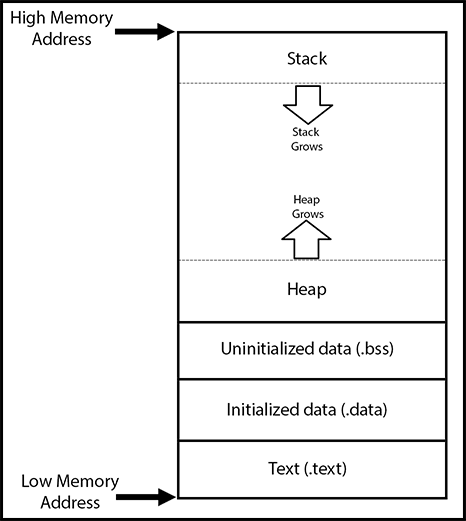
Here's what each section holds:
.text: Contains your executable code and constant data (e.g., variables declared withconst). This section lives in FLASH..data: Contains global and static variables that are initialized with a non-zero value (e.g.,int my_var = 100;). These initial values are stored in FLASH, but at startup, they are copied to RAM to be used by the program..bss: (Block Started by Symbol) Contains global and static variables that are uninitialized or initialized to zero (e.g.,int my_buffer[100];). This section does not take up space in the FLASH memory. Instead, the startup code simply reserves a block of RAM for it and clears it to zero.- Heap: A region of RAM used for dynamic memory allocation (e.g.,
malloc). It typically grows upwards from the end of the.bsssection. - Stack: A region of RAM used for function calls, passing arguments, and storing local variables. On ARM Cortex-M MCUs, the stack grows downwards from the top of RAM.
Now, let's see how these are defined within the SECTIONS command.
Bare metal embedded lecture-4: Writing linker scripts and section placement
Let's return to the Fastbit video to see how the SECTIONS command works and how it handles the critical concepts of Load Memory Address (LMA) and Virtual Memory Address (VMA).
Watch from 12:21 to 22:39. This is the most important part of the lesson. Pay close attention to the distinction made between the .text section (where VMA and LMA are the same) and the .data section (where they are different).
Let's break that down:
- VMA (Virtual Memory Address): The address where the section will be at runtime.
- LMA (Load Memory Address): The address where the section is loaded into the device by the programmer/debugger.
-
.textsection:.text : { *(.text*) *(.rodata*) } > FLASH- This places all code (
.text*) and read-only data (.rodata*) from all input files (*) into FLASH. - Here, VMA = LMA. The code is loaded into FLASH and executed from FLASH.
-
.datasection:.data : { *(.data*) } > RAM AT > FLASH- This is the key. The section's contents are placed in RAM at runtime (VMA is in
RAM), but its initial values are stored in FLASH at a different address (LMA is inFLASH). The startup code is responsible for copying the data from its LMA to its VMA beforemain()is called.
-
.bsssection:.bss (NOLOAD) : { *(.bss*) *(COMMON) } > RAM- This section only has a VMA in RAM. The
(NOLOAD)attribute tells the linker that this section has no data to be loaded from the executable file, so it has no LMA. The startup code will simply allocate this space in RAM and initialize it to zero.
3. Putting It All Together: Analyzing a Real Script
Let's look at a simplified but complete linker script for your STM32F103C8T6. This is very similar to what STM32CubeIDE generates automatically.
/* Specify the memory areas */
MEMORY
{
  FLASH (rx)      : ORIGIN = 0x08000000, LENGTH = 64K
  RAM (xrw)       : ORIGIN = 0x20000000, LENGTH = 20K
}

/* Define entry point */
ENTRY(Reset_Handler)

/* Highest address of the user mode stack */
_estack = ORIGIN(RAM) + LENGTH(RAM);

SECTIONS
{
  /* The vector table goes first in FLASH */
  .isr_vector :
  {
    . = ALIGN(4);
    KEEP(*(.isr_vector)) /* Startup code */
    . = ALIGN(4);
  } >FLASH

  /* Program code and read-only data */
  .text :
  {
    . = ALIGN(4);
    *(.text*)
    *(.rodata*)
    . = ALIGN(4);
  } >FLASH

  /* Initialized data section */
  .data :
  {
    . = ALIGN(4);
    _sdata = .;        /* Create a symbol for start of data in RAM */
    *(.data*)
    . = ALIGN(4);
    _edata = .;        /* Create a symbol for end of data in RAM */
  } >RAM AT> FLASH   /* VMA is in RAM, LMA is in FLASH */

  /* Uninitialized data section */
  .bss :
  {
    . = ALIGN(4);
    _sbss = .;         /* Create a symbol for start of .bss */
    *(.bss*)
    *(COMMON)
    . = ALIGN(4);
    _ebss = .;         /* Create a symbol for end of .bss */
  } >RAM
}
Your task: Read through this script and identify:
- The memory definitions for FLASH and RAM.
- The section where executable code (
.text) is placed. - The section for initialized data (
.data). Note its VMA and LMA. - The section for uninitialized data (
.bss). - The symbols (
_sdata,_edata,_sbss,_ebss). What do you think their purpose is? (Hint: The startup code will need them).
4. Verifying the Linker's Work with objdump
After the linker runs, you can verify its output using a command-line tool called objdump. This tool can dissect an .elf file and show you the final memory map.

Using arm-none-eabi-objdump -h your_project.elf on your own projects is a powerful way to confirm that the memory layout is exactly what you expect. It's an indispensable debugging tool for advanced memory-related issues.
Conclusion
In this lesson, we demystified the process that organizes your firmware inside the microcontroller. You learned how the linker script acts as a blueprint, commanding the linker to place different parts of your program into specific memory locations.
Key Takeaways:
- The linker script dictates the memory map of your final executable.
- The
MEMORYcommand defines the physical FLASH and RAM of the MCU. - The
SECTIONScommand maps program sections to memory regions. .text(code, constants) has its VMA and LMA in FLASH..data(initialized variables) has its VMA in RAM but its LMA in FLASH..bss(uninitialized variables) exists only in RAM and is cleared to zero at startup.- The stack grows downwards from the top of RAM, while the heap grows upwards from the
.bsssection.
We also saw that the linker script creates special symbols like _sdata and _sbss to mark the boundaries of these sections. This raises an important question: what part of the program actually uses these symbols to copy the .data section and clear the .bss section?
The answer lies in our next lesson, where we will interpret the MCU's startup file—the small, critical piece of assembly and C code that runs before main() to prepare the entire system.