Introduction
Welcome to the penultimate lesson of your capstone project! In our last session, you successfully implemented a CAN receive handler, enabling your automotive sensor node to listen and react to commands from the network. Your device is now a fully interactive member of the CAN bus, capable of both sending data and receiving instructions.
However, a professional embedded system, especially in an automotive context, must do more than just operate correctly under ideal conditions. It must be robust and predictable even when things go wrong. What happens if a sensor fails, the CAN bus disconnects, or a software task gets stuck in a loop? Simply halting in an Error_Handler() infinite loop is unacceptable.
This lesson tackles that very challenge. We will focus on the learning outcome: Integrate a system-wide error handling strategy using a dedicated error-handling task or state machine. You will learn to design and implement a centralized mechanism to detect, classify, and manage faults, transitioning your project from a functional prototype to a robust, safety-aware system.
1. From Ad-Hoc Checks to a System-Wide Strategy
So far, we've handled errors with calls like if (result != HAL_OK) { Error_Handler(); }. This is fine for development, but in a production system, it's a dead end. A robust system needs a strategy that can:
- Centralize error management instead of scattering it across the codebase.
- Classify errors to distinguish between minor issues and critical failures.
- Define clear system-level responses, such as entering a "safe state," attempting a recovery, or logging data for later analysis.
In safety-critical industries like automotive, this is governed by standards like ISO 26262. The goal is to ensure "Freedom from Interference" and to transition the system to a predictable safe state when a fault occurs.
Software for Safety-Related Automotive Systems
The 'Best Practice Guideline for Software for Safety-Related Automotive Systems' from ZVEI is an excellent industry document. You don't need to read it all, but understanding the core concepts will provide a professional foundation for our work today.
Please read the section '5.4 Mechanisms to realize freedom from interference' (you can find it on page 10 of the PDF). Focus on the descriptions for the fault classes 'Timing and Execution Faults' and 'Less Reliable QM Data Quality'. Notice how they recommend specific mechanisms like watchdogs and plausibility checks. This is the mindset we will adopt.
As the document suggests, we need architectural solutions. The two most common patterns for this in an RTOS environment are a dedicated error-handling task and a system state machine. We will combine both.
2. Architectural Design: An Error Task and a State Machine
Our strategy will be built on two pillars:
-
A Central Error-Handling Task: We'll create a high-priority FreeRTOS task,
vErrorManagerTask. Its sole job is to receive error notifications from all other parts of the system (tasks, ISRs) via a dedicated queue. This task becomes the single point of decision-making for all system faults. -
A System State Machine: The overall system will operate in one of several defined states. A fault will trigger a transition from the normal operational state to an appropriate error or degraded state.
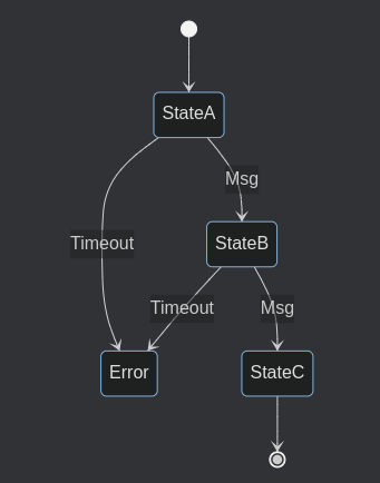
Our system states will be:
SYSTEM_STATE_STARTUP: Initializing peripherals, tasks, and communication.SYSTEM_STATE_OPERATIONAL: Everything is working correctly. The device is sensing and communicating.SYSTEM_STATE_DEGRADED_CAN: A fault with the CAN bus is detected. The device might stop transmitting but continue sensing.SYSTEM_STATE_DEGRADED_SENSOR: The temperature sensor is providing faulty data. The device might report an error over CAN but otherwise continue operating.SYSTEM_STATE_FATAL: A critical, unrecoverable error has occurred. The system will halt safely and might require a reset.
The vErrorManagerTask will manage the transitions between these states.
3. The Watchdog Pattern: Monitoring Task Liveness
How do we detect a software fault, like a task getting stuck in an infinite loop? We can't rely on that task to report an error—it's frozen! This is where the watchdog pattern comes in.
The idea is to have a supervisory task (our vErrorManagerTask) that expects to receive periodic "I'm alive" messages from other critical tasks. If a message doesn't arrive within a specified window, the supervisor assumes the task has failed and triggers a fault.
Using a Watchdog Timer with an RTOS
The article 'Using a Watchdog Timer with an RTOS' from MCU on Eclipse provides a professional implementation of this concept. We will implement a simplified version, but understanding the pattern is crucial.
Read the 'Outline' section to understand the concept of a dedicated watchdog task monitoring other 'worker' tasks. Then, review the 'Watchdog Task' section to see how it periodically runs a health check. This is precisely the logic we'll build into our error manager.
4. Implementation in the Capstone Project
Let's get to the code. We'll refactor our project to integrate this new error handling architecture.
Step 1: Define Error Codes, States, and the Error Queue
In main.c, before main(), let's define our system states, error sources, and create handles for the error queue and the system state.
/* USER CODE BEGIN PTD */
// System-wide state machine
typedef enum {
    SYSTEM_STATE_STARTUP,
    SYSTEM_STATE_OPERATIONAL,
    SYSTEM_STATE_DEGRADED_CAN,
    SYSTEM_STATE_DEGRADED_SENSOR,
    SYSTEM_STATE_FATAL
} SystemState_t;

// Sources of errors
typedef enum {
    ERROR_SRC_CAN,
    ERROR_SRC_TEMP_SENSOR,
    ERROR_SRC_LIVENESS_MONITOR
} ErrorSource_t;

// Structure for error messages
typedef struct {
    ErrorSource_t source;
    int32_t       code; // A more specific error code, if needed
} ErrorMessage_t;

/* USER CODE END PTD */

/* USER CODE BEGIN PV */
// ... (Your existing handles for tasks, semaphores, queues)

// New handles for error management
QueueHandle_t xErrorQueue;
volatile SystemState_t g_systemState = SYSTEM_STATE_STARTUP;

// Handles for task liveness check-in
SemaphoreHandle_t xCanTaskLivenessSema;
SemaphoreHandle_t xSensorTaskLivenessSema;

/* USER CODE END PV */
In main(), inside /* USER CODE BEGIN 2 */, create the queue and semaphores.
/* USER CODE BEGIN 2 */
// ... (Your existing CAN filter config, etc.)

// Create the error queue
xErrorQueue = xQueueCreate(10, sizeof(ErrorMessage_t));
if (xErrorQueue == NULL) {
    Error_Handler();
}

// Create semaphores for liveness check-in (initially empty)
xCanTaskLivenessSema = xSemaphoreCreateBinary();
xSensorTaskLivenessSema = xSemaphoreCreateBinary();

// ... (Your existing task creation calls)
/* USER CODE END 2 */
Step 2: Create the vErrorManagerTask
In your .ioc file, create a new FreeRTOS task named errorManagerTask with osPriorityHigh. Then, implement its function in main.c inside /* USER CODE BEGIN 4 */.
/* USER CODE BEGIN 4 */
// ... (Your HAL_CAN_RxFifo0MsgPendingCallback and other task functions)

void vErrorManagerTask(void *argument)
{
    ErrorMessage_t errMsg;
    TickType_t lastCanCheckin = xTaskGetTickCount();
    TickType_t lastSensorCheckin = xTaskGetTickCount();
    const TickType_t livenessTimeout = pdMS_TO_TICKS(5000); // 5 seconds

    g_systemState = SYSTEM_STATE_OPERATIONAL; // Assume startup was OK

    for(;;)
    {
        // 1. Check for error messages from the queue (wait for 1 second)
        if (xQueueReceive(xErrorQueue, &errMsg, pdMS_TO_TICKS(1000)) == pdTRUE)
        {
            // A task has reported an error
            switch (errMsg.source)
            {
                case ERROR_SRC_CAN:
                    g_systemState = SYSTEM_STATE_DEGRADED_CAN;
                    // In a real system: Log "CAN Bus Fault" via UART
                    break;
                case ERROR_SRC_TEMP_SENSOR:
                    g_systemState = SYSTEM_STATE_DEGRADED_SENSOR;
                    // In a real system: Log "Sensor Fault" via UART
                    break;
                default:
                    g_systemState = SYSTEM_STATE_FATAL;
                    break;
            }
        }

        // 2. Perform liveness monitoring (our simplified watchdog)
        if (xSemaphoreTake(xCanTaskLivenessSema, 0) == pdTRUE) {
            lastCanCheckin = xTaskGetTickCount(); // CAN task checked in
        }
        if (xSemaphoreTake(xSensorTaskLivenessSema, 0) == pdTRUE) {
            lastSensorCheckin = xTaskGetTickCount(); // Sensor task checked in
        }

        if ((xTaskGetTickCount() - lastCanCheckin) > livenessTimeout) {
            g_systemState = SYSTEM_STATE_FATAL; // CAN task is stuck!
            // In a real system: Log "FATAL: CAN Task unresponsive"
        }
        if ((xTaskGetTickCount() - lastSensorCheckin) > livenessTimeout) {
            g_systemState = SYSTEM_STATE_FATAL; // Sensor task is stuck!
            // In a real system: Log "FATAL: Sensor Task unresponsive"
        }

        // 3. Act based on the current system state
        switch (g_systemState)
        {
            case SYSTEM_STATE_OPERATIONAL:
                // All good. Blink LED slowly (e.g., every 2s)
                HAL_GPIO_TogglePin(GPIOC, GPIO_PIN_13);
                vTaskDelay(pdMS_TO_TICKS(2000));
                break;
            case SYSTEM_STATE_DEGRADED_CAN:
                // Fast blink to indicate CAN error
                HAL_GPIO_TogglePin(GPIOC, GPIO_PIN_13);
                vTaskDelay(pdMS_TO_TICKS(250));
                break;
            case SYSTEM_STATE_DEGRADED_SENSOR:
                // Pulsing blink to indicate sensor error
                HAL_GPIO_WritePin(GPIOC, GPIO_PIN_13, GPIO_PIN_RESET);
                vTaskDelay(pdMS_TO_TICKS(100));
                HAL_GPIO_WritePin(GPIOC, GPIO_PIN_13, GPIO_PIN_SET);
                vTaskDelay(pdMS_TO_TICKS(100));
                HAL_GPIO_WritePin(GPIOC, GPIO_PIN_13, GPIO_PIN_RESET);
                vTaskDelay(pdMS_TO_TICKS(100));
                HAL_GPIO_WritePin(GPIOC, GPIO_PIN_13, GPIO_PIN_SET);
                vTaskDelay(pdMS_TO_TICKS(1000));
                break;
            case SYSTEM_STATE_FATAL:
                // Solid ON LED and halt.
                HAL_GPIO_WritePin(GPIOC, GPIO_PIN_13, GPIO_PIN_RESET);
                // In a real system, you would log the error and force a system reset via the hardware watchdog.
                vTaskSuspendAll(); // Halt all other tasks
                for(;;); // Spin here
                break;
            default:
                break;
        }
    }
}
Step 3: Refactor Tasks to Report Errors and Liveness
Now, we must modify our existing tasks.
Modify vCanTxTask:
Replace any Error_Handler() calls with a queue post. Also, add the liveness check-in.
void vCanTxTask(void *argument)
{
    // ... (local variables)
    ErrorMessage_t errMsg = { .source = ERROR_SRC_CAN, .code = 0 };

    for(;;)
    {
        // Liveness check-in
        xSemaphoreGive(xCanTaskLivenessSema);

        if (xQueueReceive(xSensorDataQueue, &sensorData, portMAX_DELAY) == pdPASS)
        {
            // ... (your existing code to prepare TxHeader and TxData)

            if (HAL_CAN_AddTxMessage(&hcan, &TxHeader, TxData, &TxMailbox) != HAL_OK)
            {
                // **REPLACE** Error_Handler(); with:
                xQueueSend(xErrorQueue, &errMsg, 0);
            }
        }
    }
}
Modify vTemperatureTask:
Similarly, report liveness and post an error if the ADC read fails. We can also add a plausibility check, as suggested by the ZVEI guide.
void vTemperatureTask(void *argument)
{
    // ... (local variables)
    ErrorMessage_t errMsg = { .source = ERROR_SRC_TEMP_SENSOR, .code = 0 };
    const float minTemp = -40.0; // Plausible range for automotive
    const float maxTemp = 150.0;

    for(;;)
    {
        // Liveness check-in
        xSemaphoreGive(xSensorTaskLivenessSema);

        // ... (your existing ADC start, poll, and stop logic)

        if (HAL_ADC_PollForConversion(&hadc1, 100) == HAL_OK)
        {
            raw_adc = HAL_ADC_GetValue(&hadc1);
            // ... (your existing voltage and temperature calculation)

            // Plausibility Check
            if (temperature < minTemp || temperature > maxTemp)
            {
                errMsg.code = 1; // Code for out-of-range
                xQueueSend(xErrorQueue, &errMsg, 0);
            }
            else
            {
                // ... (your existing code to package and send data to queue)
            }
        }
        else
        {
            // ADC poll failed
            errMsg.code = 2; // Code for ADC timeout
            xQueueSend(xErrorQueue, &errMsg, 0);
        }

        vTaskDelay(pdMS_TO_TICKS(1000));
    }
}
5. Verification through Fault Injection
A robust error handling system can only be validated by testing it against faults. This practice is known as fault injection testing.
Compile and flash your new firmware. Initially, you should see the LED blinking slowly, indicating SYSTEM_STATE_OPERATIONAL. Now, let's inject some faults:
-
CAN Bus Fault: While the system is running, physically disconnect the
CAN_HorCAN_Lwire from your CAN transceiver. After a few failed transmission attempts,HAL_CAN_AddTxMessagewill return an error. YourvCanTxTaskwill send a message to the error queue, and you should see thevErrorManagerTaskchange the state toSYSTEM_STATE_DEGRADED_CAN(fast blinking LED). Reconnect the bus; the system won't auto-recover in this design, which is a valid safety choice. -
Task Liveness Fault: In
vCanTxTask, add a long delay before thexSemaphoreGive()call, likevTaskDelay(pdMS_TO_TICKS(6000));. This will simulate the task getting stuck. Re-flash the code. After about 5 seconds, thevErrorManagerTaskwill detect the missed check-in and transition toSYSTEM_STATE_FATAL. The LED will turn solid on, and the system will halt. -
Sensor Plausibility Fault: In
vTemperatureTask, temporarily force an unrealistic temperature value, for example:temperature = 200.0f;. Flash the code. The task's plausibility check will fail, it will send an error to the queue, and thevErrorManagerTaskwill transition the system toSYSTEM_STATE_DEGRADED_SENSOR(pulsing LED).
Conclusion
Congratulations! You have just implemented a professional, system-wide error handling architecture. This is a significant step that elevates your project's robustness to a level expected in commercial products, particularly in the automotive field.
Key Takeaways:
- Centralized Error Management: You created a dedicated FreeRTOS task to act as a central authority for all system faults, keeping error logic out of individual application tasks.
- System State Machine: You defined and implemented a state machine to manage the system's operational mode, allowing for graceful degradation of functionality in response to specific errors.
- Liveness Monitoring: You implemented a simplified watchdog pattern to detect non-responsive tasks, a critical technique for catching serious software failures.
- Professional Practices: You applied concepts like plausibility checks and fault injection testing, which are cornerstones of safety-critical software development.
Preview of the Final Lesson:
This was the last major technical implementation for our capstone project. You now have a complete, robust, and interactive automotive sensor node. In our final lesson, we will focus on presenting your work professionally. You will structure your project in a public Git repository, write a comprehensive README.md file, and create a short demonstration video—all essential skills for showcasing your abilities to potential employers.