Introduction
Welcome back! In our last session, we significantly enhanced our capstone project's firmware by implementing a structured, memory-managed queue. You learned how to pass pointers to data structures between FreeRTOS tasks, a technique that is both efficient and scalable. Your sensor node can now professionally package and transmit complex sensor data over the CAN bus. So far, our device is an effective "talker."
This lesson focuses on the other half of communication: "listening." We will implement a complete CAN receive handler that can parse incoming commands and control an actuator. This fulfills a key learning outcome: Implement a CAN receive handler that parses incoming commands and controls an actuator (e.g., an LED). By the end of this lesson, your device will be able to react to messages on the CAN bus, making it a truly interactive node in a network—a fundamental requirement for any automotive ECU.
1. The Challenge of Listening on a Busy Bus
The CAN bus is a broadcast network, meaning every node sees every message transmitted. In a vehicle, dozens of ECUs can be transmitting hundreds of messages per second. If our microcontroller's CPU had to process every single message to find the ones destined for it, it would be quickly overwhelmed and have no time for its primary tasks.
How do we solve this? The STM32's CAN peripheral provides two key hardware features:
- Hardware Filters: These act as a "gatekeeper," automatically rejecting messages that are not relevant to our node based on their CAN ID. This is done in hardware, requiring zero CPU intervention.
- Receive Interrupts: Instead of constantly polling the CAN peripheral to ask, "Is there a message for me yet?", we can configure it to generate an interrupt only when a message has passed the filter and is ready in a receive buffer (a FIFO).
This combination of hardware filtering and interrupts is the professional standard for building efficient and robust CAN nodes.
2. Configuring the CAN Receiver
Let's walk through the three main steps to set up our receiver: configuring the filter, enabling the interrupt, and implementing the handler function.
Step 1: Hardware Filter Configuration
The filter works by comparing the ID of an incoming message against values you program into the filter registers. You can configure it in "Identifier Mask" mode, which is very flexible. In this mode, you provide two 32-bit values: an ID and a Mask.
- The Mask register specifies which bits of the incoming ID are important. A
1means "this bit must match," and a0means "I don't care about this bit." - The ID register specifies the expected values for the bits selected by the mask.
Let's look at how the CAN ID is structured in the filter registers.
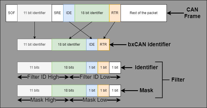
For today's exercise, we will configure our filter to accept only one specific message ID: 0x200. To do this, we set both the filter ID and the filter mask to 0x200 << 5, creating a perfect match filter.
Step 2: Enabling Receive Interrupts in CubeMX
To use the interrupt-driven approach, you need to enable the corresponding interrupt in the NVIC (Nested Vectored Interrupt Controller).
- In STM32CubeIDE, open your
.iocfile. - Go to
Connectivity->CAN. - Navigate to the NVIC Settings tab.
- Check the box for CAN1 receive FIFO 0 message pending interrupt.
This ensures the CAN1_RX0_IRQHandler will be enabled, which the HAL library uses to call our handler function.
After enabling this, regenerate the code.
Step 3: The Interrupt-Driven Workflow in Code
The process of receiving a message with HAL involves three function calls and one callback function that you will implement.
HAL_CAN_ConfigFilter(): This function, which we'll add to ourmain()function, programs the hardware filter with the settings we just discussed.HAL_CAN_Start(): This starts the CAN peripheral, allowing it to participate on the bus.HAL_CAN_ActivateNotification(): This "arms" the interrupt, telling the CAN peripheral to trigger the interrupt when a message is pending in FIFO 0.HAL_CAN_RxFifo0MsgPendingCallback(): This is the callback function that the HAL driver automatically calls from the ISR when a new message arrives. This is where we'll write our logic to parse the message and control the LED.
For a detailed walkthrough of this process, the following resource is excellent.
STM32 CAN Bus Communication Tutorial (Normal Mode)
The article 'STM32 CAN Bus Communication Tutorial' on ControllersTech provides clear, step-by-step instructions for receiving CAN data. It directly covers the concepts we're discussing.
Please read the sections titled 'Configuring CAN Filters in STM32' and 'Receiving CAN Data in STM32'. Pay close attention to the code example for CAN_FilterTypeDef and the explanation of the HAL_CAN_RxFifo0MsgPendingCallback function. This will solidify your understanding before we write the code.
3. Practical Implementation: Building the Command Handler
Now, let's integrate this into our FreeRTOS project. The goal is to control the onboard LED (PC13 on the Blue Pill) by sending it commands from your CAN-to-USB analyzer.
Our Command Protocol:
- CAN ID:
0x200 - DLC (Data Length): 1 byte
- Data[0]:
0x01: Turn LED ON0x00: Turn LED OFF
Step 1: Add Initialization Code in main()
In main.c, inside the main() function, add the following code in the /* USER CODE BEGIN 2 */ section, right before you start the FreeRTOS scheduler (osKernelStart()). This ensures the CAN peripheral is fully configured and ready to receive before any tasks run.
/* USER CODE BEGIN 2 */
// ... (Your existing semaphore and queue creation) ...

// -- Add the following CAN Receiver Configuration --

CAN_FilterTypeDef canfilterconfig;

canfilterconfig.FilterActivation = CAN_FILTER_ENABLE;
canfilterconfig.FilterBank = 0; // Use filter bank 0
canfilterconfig.FilterFIFOAssignment = CAN_RX_FIFO0;
canfilterconfig.FilterIdHigh = 0x200 << 5; // The ID to filter for, shifted
canfilterconfig.FilterIdLow = 0x0000;
canfilterconfig.FilterMaskIdHigh = 0x7FF << 5; // Match all 11 bits of the ID
canfilterconfig.FilterMaskIdLow = 0x0000;
canfilterconfig.FilterMode = CAN_FILTERMODE_IDMASK;
canfilterconfig.FilterScale = CAN_FILTERSCALE_32BIT;
canfilterconfig.SlaveStartFilterBank = 14; // Not used for single CAN peripheral

// Configure the filter
if (HAL_CAN_ConfigFilter(&hcan, &canfilterconfig) != HAL_OK)
{
    Error_Handler();
}

// Start the CAN peripheral
if (HAL_CAN_Start(&hcan) != HAL_OK)
{
    Error_Handler();
}

// Activate the notification for pending messages in FIFO 0
if (HAL_CAN_ActivateNotification(&hcan, CAN_IT_RX_FIFO0_MSG_PENDING) != HAL_OK)
{
    Error_Handler();
}

// ... (Your existing task creation) ...

/* USER CODE END 2 */
Note: Your CanTxTask also calls HAL_CAN_Start(). It's safe to call it multiple times, but for cleaner code, you could remove it from the task and rely on this single initialization.
Step 2: Implement the Callback Function
Now for the main event. Add the following code in the /* USER CODE BEGIN 4 */ section of main.c. This function overrides the default weak implementation provided by the HAL.
/* USER CODE BEGIN 4 */

// Global variables for CAN reception
CAN_RxHeaderTypeDef RxHeader;
uint8_t             RxData[8];

/**
  * @brief  Reception a CAN message in FIFO0.
  * @param  hcan: pointer to a CAN_HandleTypeDef structure that contains
  *         the configuration information for the specified CAN.
  * @retval None
  */
void HAL_CAN_RxFifo0MsgPendingCallback(CAN_HandleTypeDef *hcan)
{
    // 1. Retrieve the message from the hardware FIFO
    if (HAL_CAN_GetRxMessage(hcan, CAN_RX_FIFO0, &RxHeader, RxData) != HAL_OK)
    {
        Error_Handler();
    }

    // 2. Check if the message ID and DLC are what we expect
    //    (The hardware filter should already ensure the ID is 0x200)
    if (RxHeader.StdId == 0x200 && RxHeader.DLC == 1)
    {
        // 3. Parse the command from the data payload
        if (RxData[0] == 0x01)
        {
            // Command to turn LED ON. The Blue Pill LED is active-low.
            HAL_GPIO_WritePin(GPIOC, GPIO_PIN_13, GPIO_PIN_RESET);
        }
        else if (RxData[0] == 0x00)
        {
            // Command to turn LED OFF
            HAL_GPIO_WritePin(GPIOC, GPIO_PIN_13, GPIO_PIN_SET);
        }
    }
}

// ... (Your existing vTemperatureTask and vCanTxTask) ...

/* USER CODE END 4 */
A Professional Practice Tip: The HAL_CAN_RxFifo0MsgPendingCallback is executed in an interrupt context. For a simple action like toggling an LED, the code above is acceptable. However, for more complex processing, the best practice is to keep the ISR as short as possible. You would use the callback to send the received data to a dedicated FreeRTOS task (using a queue) or signal a task (using a semaphore) to perform the heavy lifting. You already have the skills to do this!
4. Verification with your CAN Analyzer
Now, compile and flash the updated firmware to your Blue Pill. It's time to test your work.
- Connect your CAN-to-USB analyzer to the CAN bus, ensuring it shares a common ground with your STM32 circuit.
- Open the analyzer software on your computer and configure it to match your bus speed (e.g., 500 kbit/s).
- Go to the transmit/send message section of the software.
- Send the "ON" command:
- ID:
0x200(or200in hex) - DLC:
1 - Data:
01 - Transmit the message. You should see the onboard LED of your Blue Pill turn on.
- ID:
- Send the "OFF" command:
- ID:
0x200 - DLC:
1 - Data:
00 - Transmit the message. The LED should turn off.
- ID:
To see this kind of interaction in action, the following video clip is helpful. Although it uses a logic analyzer and shows two MCUs communicating, the principle of sending a command and seeing a reaction is the same.
STM32 CAN Communication Explained | Send & Receive Data Between Two Microcontrollers
This video from ControllersTech demonstrates a working CAN bus. Watch how pressing a button on one board (sending a message) causes the LED on the other board to blink (reacting to the message). This is exactly the stimulus-response behavior you are testing now.
Watch the segment from 14:39 to 17:00. Observe how a CAN message sent from one device triggers an immediate, visible action on the other. This validates that the receiver is correctly parsing the incoming command.
Conclusion
Excellent work! You have now implemented a complete, interrupt-driven CAN receive handler. Your device is no longer just a passive data logger; it is an active participant on the network that can listen for and act on commands. This is a massive step toward building professional automotive firmware.
Key Takeaways:
- Hardware Filtering is Key: You learned to use the STM32's hardware CAN filters to efficiently select which messages to process, saving significant CPU resources.
- Interrupts over Polling: You implemented the industry-standard, interrupt-driven method for handling incoming messages using the
HAL_CAN_RxFifo0MsgPendingCallback. - Parsing Commands: You successfully defined a simple protocol and wrote code to parse the data payload of a CAN message to control an actuator (the LED).
Preview of the Next Lesson:
We now have all the individual building blocks for robust CAN communication: transmitting data with FreeRTOS and receiving commands via interrupts. In our next lesson, we will put it all together. You will build a two-node CAN bus demo, creating a small-scale network where two microcontrollers communicate bidirectionally. This will serve as a final, practical demonstration of the skills you've acquired in this module.