Introduction
Welcome to the capstone project! Over the past eleven modules, you have built a comprehensive foundation in embedded systems, from direct register manipulation and peripheral configuration (ADC, DMA, Timers, UART, I2C, SPI) to advanced concepts like FreeRTOS and professional debugging techniques. Now, it is time to integrate these skills to build a complete, job-ready project.
This final module will guide you through the development of an Automotive Sensor Node. This project will serve as the centerpiece of your professional portfolio.
Today's lesson addresses the first and most critical step of any complex project: designing the software architecture. Before writing a single line of application code, a professional engineer creates a blueprint. This blueprint defines the system's components, their responsibilities, and how they interact. Our goal is to design a robust, scalable, and maintainable architecture for our multi-sensor data logger using FreeRTOS.
We will deconstruct the project requirements, apply key architectural principles, and produce a clear design that will guide our implementation in the lessons to come.
1. Understanding the System Context
Our project is an "Automotive Sensor Node". At a high level, its purpose is to acquire data from its environment, process it, and communicate it over a CAN bus, while also being able to receive commands. This is a common pattern in modern vehicles, where dozens of Electronic Control Units (ECUs) perform similar functions.
To visualize where our device fits, consider this typical system diagram:
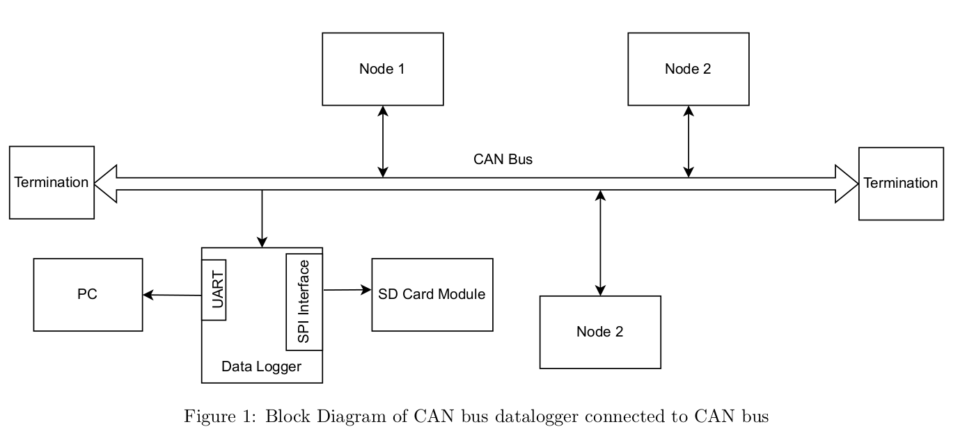
Defining the Core Requirements
Based on the upcoming lessons in this module and the hardware you have, our sensor node must perform the following functions concurrently:
- Sensor Acquisition 1: Periodically read the MCU's internal temperature sensor.
- Sensor Acquisition 2: Periodically measure the distance using the ultrasonic sensor.
- Data Transmission: Package the sensor data (temperature and distance) into a CAN message and transmit it on the bus every second.
- Command Reception: Listen for incoming CAN messages. If a specific command message is received, toggle the user LED.
- Status Display: Continuously update the I2C LCD with the latest sensor readings and system status.
- System Health: Blink an onboard LED at a fixed rate to provide a visual "heartbeat," indicating that the system is running.
Handling all these tasks in a single while(1) loop would result in complex, unmanageable "spaghetti code." This is precisely the problem an RTOS is designed to solve.
2. Architectural Principles: Building a Solid Foundation
A good architecture makes a system easy to understand, maintain, and extend. Before we start drawing boxes and arrows, let's establish the principles that will guide our design.
How to Create a Software Architecture | Embedded System Project Series #6
This video from Artful Bytes provides an excellent overview of why software organization is crucial and introduces the core principles we will be using, such as layered architecture and decoupling.
Please watch the following segments: The 'Why' (02:29 - 05:56): Focus on the reasons for organizing software, especially the points about maintainability, portability, and testability. Layered Architecture Intro (06:06 - 07:16): Pay attention to the distinction between the hardware-dependent 'driver' layer and the hardware-independent 'application' layer. Guiding Principles (19:08 - 21:30): This section summarizes key concepts like decoupling, modularity, and encapsulation. We will apply these directly to our design.
The key takeaways from the video are:
- Layered Architecture: We will separate our application logic (what the system does) from the low-level drivers (how it talks to the hardware).
- Decoupling: Our tasks should be as independent as possible. They should not know about the internal workings of other tasks.
- Modularity: We will group related functions into modules (e.g., an
adc_drivermodule, acan_drivermodule). - Encapsulation: We will hide implementation details. For example, the application layer will call a function like
CAN_SendMessage()without needing to know which specific registers are being written to.
3. Decomposing the System into FreeRTOS Tasks
With our requirements and principles in mind, let's break the system down into a set of independent, concurrent tasks. Each task will have a single, well-defined responsibility.
When is it a Good Time to Use FreeRTOS?
This resource provides a concise summary of when and why to use an RTOS, along with practical examples of how to structure an application with tasks. It will help us map our requirements to specific FreeRTOS tasks.
Read the sections "Use FreeRTOS When:" and the recommended task breakdown in "example 2". Notice how different functionalities like reading sensors and communication are split into separate tasks.
Applying this thinking, we can identify the following tasks for our system:
-
TemperatureTask(Medium Priority):- Responsibility: Periodically trigger an ADC conversion to read the internal temperature sensor.
- Period: Every 1000ms.
- Action: Send the resulting temperature value to a queue for other tasks to consume.
-
DistanceTask(Medium Priority):- Responsibility: Trigger the ultrasonic sensor and use a timer in Input Capture mode to measure the echo pulse width.
- Period: Every 250ms.
- Action: Calculate the distance and send it to a queue.
-
CanTxTask(Medium Priority):- Responsibility: Consolidate the latest data from all sensors.
- Period: Every 1000ms.
- Action: Format the data into a CAN message and transmit it.
-
CanRxTask(High Priority):- Responsibility: Process incoming CAN messages.
- Trigger: Awakened by an ISR when a CAN message is received.
- Action: Parse the message. If it's a valid command, perform the requested action (e.g., toggle the LED).
-
DisplayTask(Low Priority):- Responsibility: Update the I2C LCD screen.
- Trigger: Awakened when new data is available or on a periodic basis (e.g., every 500ms).
- Action: Format and display the latest sensor values and system status.
-
HeartbeatTask(Lowest Priority):- Responsibility: Provide a visual indication that the scheduler is running.
- Period: Toggle an LED every 500ms.
4. Designing Inter-Task Communication and Synchronization
Now that we have our tasks, we must define how they will safely communicate and share resources. We will use FreeRTOS primitives for this.
Let's revisit the freertos-dat resource to see concrete pseudocode examples of using queues and mutexes for the exact patterns we need.
Review the sections on "Inter-Task Communication" and "Pseudocode Overview". Focus on how a QueueHandle_t is used to send a struct from a sensor task to a display task, and how an i2c_mutex is used to protect the shared I2C bus.
Based on these patterns, we can define our communication mechanisms:
-
Queues for Data Passing:
temperatureQueue: A queue to hold a singlefloatvalue.TemperatureTaskwill write to it, andCanTxTaskandDisplayTaskwill read from it.distanceQueue: A queue to hold a singleuint16_tvalue (distance in cm).DistanceTaskwill write to it, andCanTxTaskandDisplayTaskwill read from it.
-
Semaphores for Synchronization:
canRxSemaphore(Binary Semaphore): The CAN receive ISR will 'give' this semaphore whenever a new message arrives in the hardware FIFO. TheCanRxTaskwill 'take' this semaphore, waking it from a blocked state to process the message. This decouples the short, fast ISR from the longer processing task.
-
Mutexes for Resource Protection:
i2cMutex(Mutex): The I2C bus is a shared resource. In our case, only theDisplayTaskuses it. However, if we were to add another I2C sensor in the future, we would need a mutex. It's good practice to design for this. Any task wanting to use the I2C peripheral must first take the mutex and release it when done.
5. The Complete Software Architecture
By combining the tasks, communication channels, and layered principles, we can now visualize our complete software architecture.
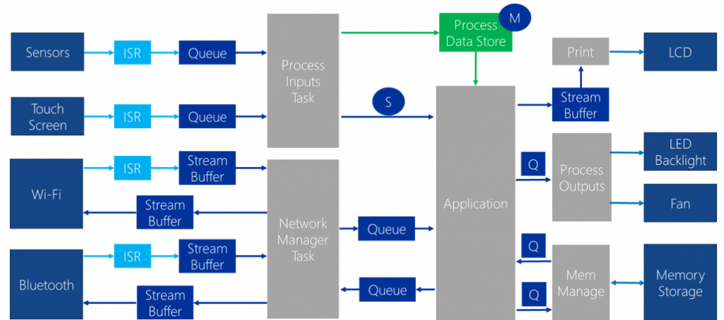
Our specific architecture for the Automotive Sensor Node looks like this:
Architectural Diagram
+----------------------------------------------------------------------------------+
| APPLICATION LAYER (Hardware Independent Logic)                                   |
|                                                                                  |
|  +----------------+   +----------------+      +--------------+   +-------------+  |
|  | HeartbeatTask  |   | TemperatureTask|      | DistanceTask |   | CanRxTask   |  |
|  | (Lowest Prio)  |   |  (1000ms)      |      |  (250ms)     |   | (Event-D...)<-+-- (CAN ISR gives Semaphore)
|  +-------+--------+   +-------+--------+      +-------+------+   +------+------+  |
|          |                |                         |                 |          |
|          v                v (temp)                  v (dist)          v          |
|  +-------+--------+   +---+-------------+       +---+----------+   +--+---+-----+  |
|  | DRV_LED_Toggle |   | temperatureQueue  |       | distanceQueue  |   | DRV_LED_  |  |
|  +----------------+   +-----------------+       +----------------+   | Toggle    |  |
|                               |                         |            +-----------+  |
|          +--------------------+-------------------------+                           |
|          |                                              |                           |
|          v (peek)                                       v (peek)                    |
|  +-------+--------+                             +-------+--------+                  |
|  |   DisplayTask  |                             |    CanTxTask   |                  |
|  | (Low Prio, 500ms)|                           | (1000ms)       |                  |
|  +-------+--------+                             +-------+--------+                  |
|          | (Take Mutex)                                 |                           |
|          v                                              v                           |
+----------------------------------------------------------------------------------+
| DRIVER / HAL LAYER (Hardware Dependent)                                          |
|                                                                                  |
|  +----------------+   +----------------+      +--------------+   +-------------+  |
|  |  DRV_I2C_Write |   | DRV_ADC_Read   |      | DRV_TIM_Capture|   | DRV_CAN_Tx/Rx| |
|  +----------------+   +----------------+      +--------------+   +-------------+  |
|                                                                                  |
+----------------------------------------------------------------------------------+
| HARDWARE (STM32F103 Peripherals)                                                 |
+----------------------------------------------------------------------------------+
Data and Control Flow:
- The
TemperatureTaskandDistanceTaskrun on their respective schedules, calling functions from the Driver Layer (DRV_ADC_Read,DRV_TIM_Capture) to get raw data. They process this data and post the results to their respective queues. - The
DisplayTaskandCanTxTaskalso run on timers. They don't read the queues destructively; instead, they can peek at the latest value to update the LCD or build a CAN message. - When a CAN message arrives, the hardware triggers a CAN ISR. The ISR does the minimum work possible: it retrieves the message from the hardware and gives the
canRxSemaphore. - The
CanRxTask, which was blocked waiting for the semaphore, wakes up, processes the message, and toggles the LED via a driver function. - All tasks run independently, managed by the FreeRTOS scheduler, creating a responsive, concurrent system.
6. A Note on Scalable Task Initialization
As your system grows, adding more and more xTaskCreate(...) calls in main.c can become messy. A more professional and scalable approach is to use a configuration table.
A Simple, Scalable RTOS Initialization Design Pattern
This article from Beningo Embedded introduces a clean design pattern for initializing RTOS tasks. While we will use the simpler method for now, this is an excellent pattern to be aware of for professional development.
Read through the article to understand the three main steps: creating a task parameter structure, building a configuration table (an array of those structures), and looping through the table to create all tasks. This keeps all your task configurations neatly in one place.
This pattern centralizes all task parameters—name, function, stack size, priority—into a single array. This makes it trivial to see all tasks in the system at a glance and makes adding, removing, or re-configuring tasks much cleaner.
Conclusion
In this lesson, we have laid the complete architectural foundation for our capstone project. By starting with a high-level design, we have created a clear, professional blueprint that will make the implementation process smoother and more organized.
Key Takeaways:
- Decomposition is Key: A complex problem was broken down into a set of simple, single-responsibility FreeRTOS tasks.
- Architecture Defines Interaction: We identified the specific FreeRTOS primitives (queues, semaphores) needed for tasks to communicate and synchronize safely and efficiently.
- Layers Create Abstraction: Our design clearly separates the application logic (the "what") from the hardware drivers (the "how"), making the system more portable and easier to test.
- The Design is Our Roadmap: The architecture diagram we created will be our guide for the upcoming implementation lessons.
Preview of the Next Lesson:
With our design complete, it's time to start coding. In the next lesson, you will implement the first part of our architecture. You will create a FreeRTOS task that periodically reads the internal temperature sensor using the ADC and DMA, just as we have designed.