Hello! In our last lesson, we set the stage for optimal control by formulating the Linear Quadratic Regulator (LQR) problem. We defined the cost function and understood that the weighting matrices and represent the penalty on state error and control effort, respectively.
This lesson gets to the heart of LQR design. We'll move from the "what" to the "how," focusing on practical strategies for selecting the and matrices. Your goal is to learn how to intelligently choose and tune these matrices to balance the trade-off between how well your system performs and how much energy it uses to do so. This is arguably the most crucial skill in applying LQR in the real world.
1. It's All About the Ratio
Before diving into tuning, it's essential to grasp one key concept: in the LQR cost function, it's the ratio of the weights in and that matters, not their absolute values.
Consider the cost function:
If we multiply both and by the same positive scalar, say 10, the cost function becomes:
Minimizing yields the exact same optimal gain matrix as minimizing . This means that a controller designed with and is identical to one designed with and .
This insight simplifies the design process: you can often fix one matrix (e.g., set , where is the identity matrix) and tune the other.
- High ratio: Penalizes state error heavily. Leads to a fast, aggressive response with high control effort.
- Low ratio: Penalizes control effort heavily. Leads to a slow, conservative response with low control effort.
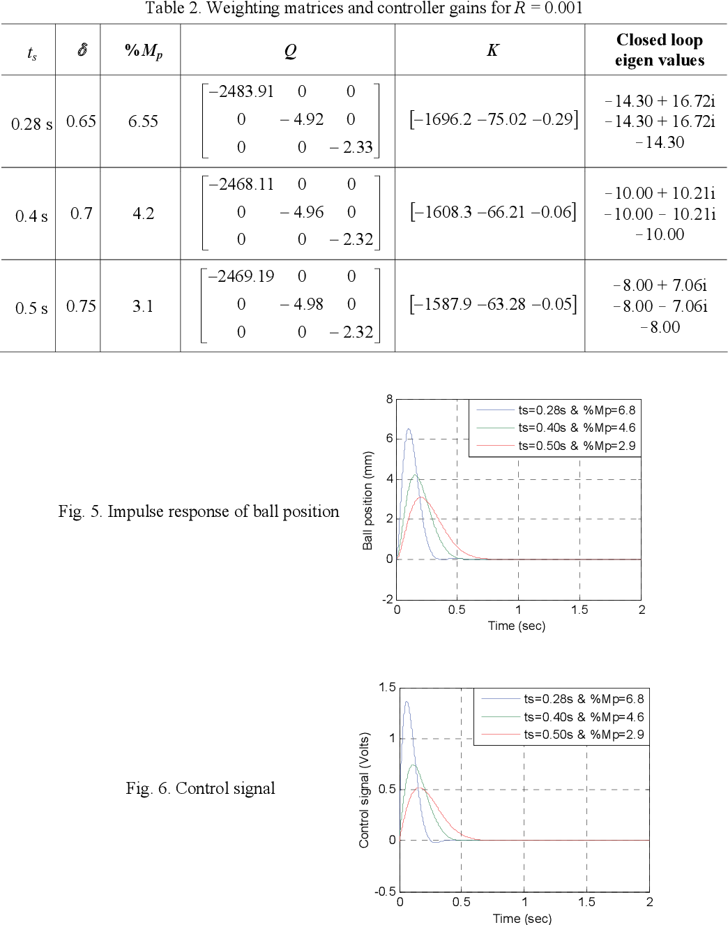
The following image provides a perfect illustration of this trade-off. For a fixed , as the weights in are increased, the system responds faster and with less overshoot, but the required control signal becomes much larger.
2. A Systematic Start: Bryson's Rule
So, how do you pick the initial values for and ? Choosing them randomly is inefficient. A widely used heuristic for a good starting point is Bryson's Rule.
The rule provides a way to scale the penalties based on the maximum acceptable deviations for each state and control input.
lqr - Linear-Quadratic Regulator (LQR) design - MATLAB
This page from the MATLAB documentation for the lqr command gives the formal definition of Bryson's Rule. It provides a concrete formula for your initial Q and R matrices.
Please read the section under 'Input Arguments', focusing on the descriptions for 'Q' and 'R'. Pay attention to the equations provided for Bryson's rule.
As the documentation describes, the rule is as follows:
The diagonal elements of and are set to the inverse of the squared maximum acceptable value for the corresponding state or input. The off-diagonal elements are typically set to zero.
This is a form of normalization. By scaling each component this way, you make a 1-unit deviation in each scaled state or input equally "costly," providing a sensible and balanced starting point for your design.
Example for your Inverted Pendulum:
Let your state vector be . Suppose your design requirements are:
- Cart position should not deviate more than 0.5 meters.
- Pendulum angle should not deviate more than 0.1 radians ().
- Motor force should not exceed 10 Newtons.
You might not have hard limits for the velocities, so you can estimate them. Let's say max cart velocity is 1 m/s and max pendulum angular velocity is 2 rad/s.
Using Bryson's rule, your initial diagonal and would be:
This gives you a starting point: and . Notice that this initial guess already heavily penalizes the pendulum angle , which aligns with the physical goal of keeping it upright.
3. The Iterative Design Process
Bryson's rule gives you a good first guess, but LQR design is fundamentally an iterative, trial-and-error process. You start with an initial and , simulate the response, and then tune the matrices until the performance meets your requirements.
The following resources show this iterative process in action.
What Is Linear Quadratic Regulator (LQR) Optimal Control? | State Space, Part 4
This MATLAB video provides a very intuitive visual demonstration of tuning. Watch how tweaking Q and R affects the performance of a simple model.
Watch from 9:45 to 15:45. Observe the 'UFO' example. The presenter starts with baseline Q and R matrices and then iteratively adjusts them to either save fuel (by increasing R) or speed up the response (by increasing Q), showing the direct impact of each change.
Now, let's look at an example that is directly relevant to your pendulum project. This resource walks through the exact process of tuning for an inverted pendulum.
Inverted Pendulum: State-Space Methods for Controller Design
This tutorial for the inverted pendulum demonstrates a practical tuning workflow. It starts with an initial controller, identifies its shortcomings, and then modifies the Q matrix to achieve the desired performance.
Read the text starting from the line 'The element in the (1,1) position of Q represents the weight on the cart's position...' down to the end of the LQR section (before 'Adding precompensation'). Focus on how they diagnose the initial response plot as unsatisfactory and then decide to increase specific elements in Q to improve it.
Test your understanding!
You're designing an LQR controller for your rotary inverted pendulum. The state vector is , where is the arm angle and is the pendulum angle.
You use and and find that the pendulum is stable, but it oscillates too much (i.e., is too large during stabilization) and the response is a bit slow overall.
What two changes would you make to your and matrices to address these issues?
Show answer
-
Address pendulum oscillation: To reduce the pendulum's angular velocity, you should increase the penalty on the state. You would increase the fourth element of the diagonal matrix, for example, changing it from 1 to 10. So, becomes .
-
Speed up the overall response: To make the controller more aggressive and the response faster, you need to increase the overall ratio. You can achieve this by either scaling the entire matrix up or by decreasing the value. For example, you could change from
[1]to[0.1].
So, a good next iteration would be to try and .
4. Practical Tuning Strategies
Summarizing the process, here is a workflow for tuning your LQR controller:
-
Set an Initial Guess: Use Bryson's Rule to get a reasonable starting point for your diagonal and matrices. If you don't have hard limits, starting with identity matrices () is also common.
-
Simulate and Analyze: Run a simulation with your initial controller. Look at the state trajectories and the control input. Does the system meet your performance criteria (settling time, overshoot)? Is the control input within the physical limits of your actuator?
-
Tune the Ratios:
- Overall Performance: If the response is too slow, increase the overall ratio. You can do this by multiplying your entire matrix by a factor (e.g., 10) or dividing your matrix by a factor. If the control effort is too high and saturating your actuator, do the opposite (decrease or increase ).
- Specific State Performance: If a particular state is not behaving as desired (e.g., too much overshoot, slow to settle), increase the corresponding diagonal element in the matrix. This tells the controller to prioritize regulating that specific state.
-
Iterate: Repeat steps 2 and 3. The process is a loop: design -> simulate -> analyze -> repeat. Don't be afraid to make large changes to the weights (factors of 10 or 100) to see a clear effect on the response.
This iterative process, guided by physical intuition about your system, is the essence of practical LQR design.
Conclusion
In this lesson, you've learned the practical art of selecting and tuning the LQR weighting matrices. You now have a framework for translating high-level performance goals into the numbers that define the LQR cost function.
Key Takeaways:
- LQR design is an iterative process of selecting and to balance performance and effort.
- Only the ratio of to matters.
- Bryson's Rule provides a systematic, physics-based method for choosing initial values for and .
- Tuning involves adjusting the ratio for overall aggressiveness and modifying individual diagonal elements of to improve the response of specific states.
Preview of the Next Lesson:
We now know how to formulate the LQR problem (Lesson 1) and how to select the design parameters and (this lesson). But we've been treating the lqr command in MATLAB as a black box. In the next lesson, we will peek inside that box to understand how the optimal gain is actually calculated. We'll introduce the Algebraic Riccati Equation (ARE), the mathematical cornerstone that provides the solution to the LQR problem.