Hello! Let's dive into the next topic in our exploration of MIMO control.
In the previous lesson, we learned how to simulate a closed-loop system to verify its performance after designing a state feedback controller . We saw that this single gain matrix, , influences the entire system at once. This works, but it treats the system as a single, interconnected block. What if we could simplify the problem?
Today's lesson addresses the learning outcome: Analyze a MIMO system for input-output decoupling possibilities using static state feedback.
In many multivariable systems, a single input affects multiple outputs, and a single output is affected by multiple inputs. This "crosstalk" or coupling makes controller design complex. Decoupling is a powerful technique that aims to cancel out these interactions, allowing us to control each output with a single, dedicated input, effectively turning one big MIMO problem into several smaller, independent SISO problems. Your background in signal processing, where you deal with crosstalk between channels, provides a great parallel to this concept.
Our goal today is not to design the controller itself, but to determine if a given system is a candidate for this elegant simplification.
The Goal: A Diagonal System
Ideally, we would want our system to be naturally decoupled. For a 2-input, 2-output system, this would look like the diagram below, where the controller K(s) is diagonal.
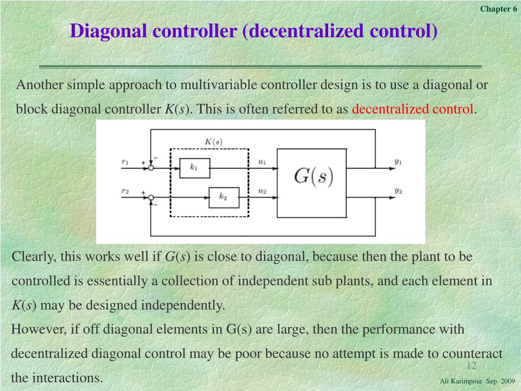
As the diagram explains, this simple "decentralized" approach works well only if the plant G(s) is already "nearly diagonal"—meaning the interactions between channels are weak. But what if they are strong, as is often the case? Your rotary pendulum is a prime example: the motor torque you apply (input) affects both the arm's angle and the pendulum's angle (outputs) in a highly coupled way.
This is where decoupling with state feedback comes in. Instead of hoping the plant is diagonal, we design a controller that makes the closed-loop system appear diagonal to a new set of command inputs.
The Decoupling Control Law
To achieve decoupling, we use a slightly more general state feedback control law than the one we've seen so far:
Here:
- is the state vector.
- is the vector of control inputs to the plant.
- is a new vector of external command inputs. This is what we, the designers, will use to send commands to the system.
- is the state feedback gain matrix.
- is a feedforward (or input) gain matrix.
Our goal is to choose and such that the transfer function from our new commands to the system outputs is diagonal. This means will only affect , will only affect , and so on, with no cross-coupling.
This technique is used in many advanced applications, such as controlling the orientation and flexible modes of a large space structure independently. The following document discusses this exact application.
Decoupling and Observation Theory Applied to Control of a Long Flexible Beam in Orbit
This NASA technical paper, 'Decoupling and Observation Theory Applied to Control of a Long Flexible Beam in Orbit', provides excellent motivation for why decoupling is so useful in complex systems.
Please read the 'INTRODUCTION' section, and then look at the 'BASIC EQUATIONS' in Figure 2 and the accompanying text. Finally, skim the first paragraph of the 'DYNAMIC CHARACTERISTICS' section. Focus on these points: The stated goal: "independent control of each state" or mode. The form of the control law used (note the v command vector). The mention of 'control-influence coefficients' in the B matrix, which are key to achieving decoupling.
As you saw, the paper frames decoupling as a way to manage complex systems by controlling different aspects (like pitch attitude and flexible modes) independently. The ability to do this hinges on the system's intrinsic properties, captured by the A, B, and C matrices.
The Condition for Decoupling
So, how do we know if a system can be decoupled using this method? The answer lies in a specific analytical test. Let's consider a linear time-invariant (LTI) system with inputs and outputs:
(For simplicity, we assume the direct feedthrough matrix is zero, which is true for most mechanical systems, including the inverted pendulum).
The key idea is to see how "quickly" each input affects each output . We do this by repeatedly differentiating the outputs until an input appears.
-
Differentiate the output: The -th output is , where is the -th row of the matrix . Its first derivative is:
-
Check for input influence: The term is a row vector that shows the direct influence of the input vector on the rate of change of . If this vector is not all zeros, the input appears, and we stop.
-
Differentiate again if needed: If , it means the input has no instantaneous effect on the first derivative of . So, we differentiate again:
Now, we check the term . If it's a non-zero row vector, we stop.
We repeat this process for each output and find the smallest integer , called the relative degree of the output, such that:
and
Once we have found the relative degree for each of the outputs, we construct a matrix called the decoupling matrix, denoted as . The -th row of this matrix is the first non-zero row vector we found in the differentiation process:
The Decoupling Condition:
A MIMO LTI system can be decoupled by static state feedback if and only if its decoupling matrix is nonsingular (i.e., it is invertible, or its determinant is non-zero).
Example Analysis
Let's walk through an example. Consider a 3-state, 2-input, 2-output system with the following matrices:
Let's analyze its decoupling capability.
Step 1: Analyze Output
- The first row of C is .
- Calculate :
This is a zero vector, so we must differentiate again. The relative degree . - Calculate :
This is not a zero vector. So, we stop. The relative degree for the first output is . - The first row of our decoupling matrix is .
Step 2: Analyze Output
- The second row of C is .
- Calculate :
This is not a zero vector. So, we stop. The relative degree for the second output is . - The second row of our decoupling matrix is .
Step 3: Construct and Evaluate
Combining the rows we found:
This is the identity matrix. Its determinant is 1, which is non-zero. Therefore, the matrix is nonsingular.
Conclusion: Yes, this system can be decoupled using static state feedback.
Test your understanding!
Consider a system where the analysis yields a decoupling matrix:
Can this system be decoupled using static state feedback? Why or why not?
Show answer
No, this system cannot be decoupled. The determinant of is . Since the decoupling matrix is singular (not invertible), the condition for static state feedback decoupling is not met. Physically, this means that the two inputs have a fundamentally redundant effect on the outputs that cannot be untangled with this type of control law.
Conclusion
In this lesson, we introduced the powerful concept of input-output decoupling. By transforming a complex, interacting MIMO system into a set of simple, non-interacting SISO systems, we can make the controller design process significantly more manageable.
Key Takeaways:
- Coupling (or interaction) is when a system's inputs affect multiple outputs simultaneously, complicating control.
- Decoupling uses a state feedback law of the form to make the closed-loop system appear diagonal from the perspective of a new command input vector .
- A system's suitability for decoupling can be rigorously tested before starting the design.
- The test involves calculating the decoupling matrix and checking if it is nonsingular.
Preview of the Next Lesson:
We've just learned how to answer the question, "Can this system be decoupled?". The natural follow-up is, "If so, how?". In our next lesson, we will do exactly that: Design a decoupling state feedback control law for a given system, if possible. We will learn the formulas for calculating the required feedback matrix and feedforward matrix that achieve the desired decoupling.