Hello! In the previous lesson, you calculated three-phase power at a specified measurement point. A BESS has several such points, separated by conversion equipment and transformers. To understand what a power reading means—and eventually what a power plant controller should control—you first need to locate it on the electrical path.
This lesson uses a simplified single-line diagram to follow a discharge from battery blocks to the medium-voltage collection network, then extends the path to the point of interconnection (POI). You will also follow the same equipment in reverse during charging.
What the single line represents
A single-line diagram, or SLD, compresses an electrical system into a readable drawing. On the AC side, one line stands for a three-phase connection; it does not mean the plant has only one conductor. The drawing emphasizes which equipment is connected and in what order, rather than showing where each enclosure sits on site.
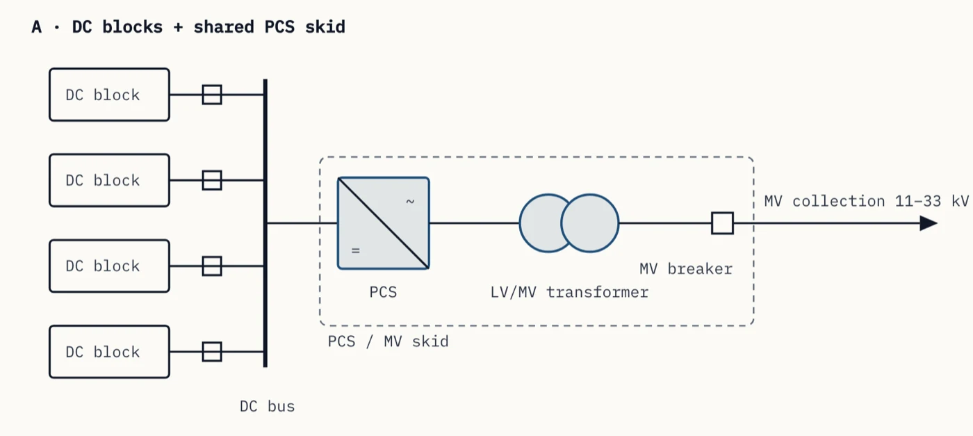
Start at the four rectangles on the left. Each is labelled DC block. The small square on each branch represents a DC-side disconnect or fused connection in this example. The branches meet at the heavy vertical DC bus, which feeds one shared power conversion system (PCS). Inside the dashed skid boundary, the PCS is followed by a low-voltage/medium-voltage (LV/MV) transformer and an MV breaker.
The right-pointing mark at the MV collection feeder is useful for tracing a discharge, but do not mistake it for a claim that the equipment works in only one direction. Charging uses the connected path in reverse. Nor does an SLD like this tell you whether a particular breaker is open right now: it shows the electrical arrangement, not a live status display.
The conversion boundary: DC becomes AC
On discharge, the battery blocks supply direct current (DC). The PCS converts that DC into alternating current (AC) suitable for its AC connection. The LV/MV transformer then changes the AC voltage level for the collection network. The transformer is not the device that converts DC to AC.
Watch the PCS portion of Gaurav J – TheElectricalGuy’s Battery Energy Storage System | BESS | All Components Explained for a physical explanation of this two-way conversion.
Battery Energy Storage System | BESS | All Components Explained
Gaurav J – TheElectricalGuy explains why batteries need a PCS to exchange power with an AC grid. Watch for the distinction between the PCS's charging and discharging roles.
Watch the PCS explanation. Focus on which side of the PCS is DC, which side is AC, and what the conversion does in each direction; the voltages quoted for the featured unit are an example, not values to assume for every BESS.
Now trace the pictured discharge one component at a time. DC power leaves the battery blocks, passes their DC-side connections, and combines on the DC bus. The shared PCS converts it to AC. That AC passes through the skid’s LV/MV transformer, then the MV breaker, and enters the MV collection feeder. Multiple skids may connect to that feeder in a larger plant; this drawing shows just one branch.
This order is more informative than simply saying “the batteries feed the grid.” In particular, a measurement at the PCS AC terminals is upstream of the skid transformer and collection system. It is not automatically a measurement of power at the grid connection.
The path beyond the pictured feeder
The illustration stops at MV collection; it does not show the POI. To see how this branch fits into a whole-plant path, read the site-level description and the MV-skid description in Sergey Syrvachev’s Battery Energy Storage System Diagram (BESS Block Diagram).
Battery Energy Storage System Diagram (BESS Block Diagram)
Sergey Syrvachev's site-level diagram places the energy station and its transformer between the battery equipment and the grid connection. Read it to extend the cropped SLD without assuming that its right edge is the POI.
In “1 · The whole site, at a glance,” read the site path in the opening paragraph; it describes the route from the grid toward the batteries, so mentally reverse it for discharge. Then, in “3 · The MV skid — PCS and transformer,” read the skid description. Distinguish its LV/MV transformer from any separate grid step-up transformer elsewhere on the site.
For a plant with the arrangement described there, the discharge continues from the MV collection network through any plant-level grid step-up (GSU) transformer and associated connection equipment to the POI, the defined connection with the grid. Not every project has a GSU between its MV collection network and POI; the actual SLD and connection definition determine the route. The figure above establishes neither a GSU nor a POI meter, so neither should be silently added inside its dashed skid or at its right-hand edge.
Two transformer names can otherwise cause confusion:
- The skid LV/MV transformer raises the PCS’s AC output to the MV collection voltage in the pictured discharge path.
- A plant-level GSU transformer, where present, connects the collected plant output to another grid voltage level farther along that path.
Both act on AC. Neither replaces the PCS. If a project drawing shows a meter, identify its exact position rather than assuming that “plant power,” “PCS power,” and “POI power” refer to the same location. A meter associated with the POI may also be installed at a location specified by the project’s metering arrangement.
Follow charging back to the batteries
During charging, power enters from the grid side and travels through the same connected equipment in the opposite direction. It passes any applicable plant-level transformer and the MV collection network, then the skid’s MV breaker and LV/MV transformer. AC arrives at the PCS, which converts it to DC. From the DC bus, the charging power reaches the connected battery blocks through their individual DC-side branches.
The physical distinction remains the same in either direction: the batteries and their DC connections are on one side of the PCS; the transformer, MV collection, and grid connection are on its AC side. The direction of active-power flow changes, but the locations of the components do not. In the next lesson, you will give charging and discharging readings signed values using explicitly stated meter and inverter conventions; direction alone does not tell you which sign a particular device displays.
An SLD may also include control or communication information on other drawings. Do not treat the power conductors in this figure as PPC command paths. For a PPC, the immediate value of tracing this SLD is knowing which equipment its plant-level measurement includes and which equipment lies between that measurement and a PCS.
Recognizing a different one-line arrangement
The pictured station uses one shared PCS on a DC bus. That is common, but not the only BESS arrangement. Read the short archetype comparison in BESS Single-Line Diagram (SLD): Layouts & One-Line Examples to learn what changes when conversion is distributed among units.
BESS Single-Line Diagram (SLD): Layouts & One-Line Examples
The archetype comparison shows why you should locate the DC/AC boundary on each project drawing rather than assume every battery block feeds one shared PCS.
Immediately before the heading “One-line archetypes across the six standard site layouts,” read the three opening paragraphs labelled “Archetype A,” “Archetype B,” and “Archetype C.” Begin with the three layouts. For each, identify whether the units join on a DC bus or an AC bus, and locate the transformer after the PCS output.
In archetype A, as in our figure, battery blocks join on DC before one PCS. In archetype B, each container has a smaller PCS, and their outputs join on a low-voltage AC bus before a shared transformer. In archetype C, battery and inverter are integrated within each unit; their outputs are already AC when they join the shared LV side. The connection details differ, but you can still trace each unit from battery-side DC, through a PCS, onto an AC network, and toward the grid connection.
Key takeaways
To read a BESS SLD, find the batteries, locate the PCS where DC and AC meet, and then follow the AC conductors through transformers, switching equipment, collection network, and ultimately the defined POI. The provided figure shows only part of that route: it ends at MV collection, not at the POI. Trace charging in the opposite direction, and check each drawing rather than assuming every plant shares the same bus or transformer arrangement.
Next, you will use this physical route to distinguish power-flow direction from the positive and negative signs reported by different meters and inverters.