Hello! Welcome back to our course on Fusion 360.
In our last lesson, we focused on refining sketches with the Trim, Extend, and Offset tools. These commands are essential for manipulating geometry that you've already drawn. Today, we'll shift our focus to a powerful strategy for creating geometry more efficiently from the very beginning: symmetry. Many of the items you plan to design—from gaming accessories to household parts—are symmetrical. By mastering the Mirror command, you only need to design and constrain half of your part, and Fusion 360 will do the rest.
This lesson will teach you how to create perfectly symmetrical sketches using construction lines as a guide for the Mirror command. This technique not only saves a significant amount of time but also embeds your design intent, ensuring that your model updates predictably when you make changes.
1. The Role of Construction Lines
Before you can mirror a sketch, you need a centerline or axis to mirror it across. In Fusion 360, this is the job of a construction line.
A construction line is a special type of line used for reference and layout purposes. It is visible and usable within the sketch environment for alignment, constraining, and as a mirror axis, but it is ignored by 3D commands like Extrude. This means it won't divide your profile or interfere with creating solid bodies.
To create a construction line:
- Draw a line as you normally would using the
Linetool (shortcutL). - Select the line.
- Press the
Xkey on your keyboard, or click the "Construction" option in the Sketch Palette.
The line will change from a solid blue or black line to a dashed one, indicating it's now a construction line. For symmetrical designs, it's common practice to place this construction line along one of the primary axes (like the Y-axis for vertical symmetry).
2. The Mirror Command
With a construction line in place, you can use the Mirror command to do the heavy lifting. The command duplicates selected sketch geometry across your construction line.
The core concept is simple: you draw and fully constrain one half of your design, and then mirror it to create a complete, perfectly symmetrical whole.
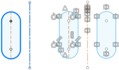
Now, let's watch a detailed video that walks through the entire process, including common pitfalls and best practices.
How to Mirror Sketch Geometry in Fusion 360
This video from Product Design Online provides a comprehensive look at the Sketch Mirror command. It clearly explains not just the 'how,' but also the 'why' behind the associated constraints.
Please watch the following segments: The Basic Workflow (0:58 - 3:05): Pay close attention to how the 'Objects' and 'Mirror Line' are selected. Note the common mistake of accidentally including the mirror line itself in the object selection (2:30). Symmetry Constraints (4:24 - 5:30): This is the most important part. Observe how changing a dimension on the original side automatically updates the mirrored side. This is the power of parametric symmetry. Construction Lines and Closed Profiles (7:17 - 8:15): This section demonstrates why using a construction line (instead of a solid line) as the mirror axis is crucial for creating a single, closed profile ready for extrusion.
3. Understanding Symmetry Constraints
As the video demonstrated, the Mirror command does more than just copy geometry. It creates a lasting relationship between the original and the mirrored elements using Symmetry Constraints. You can see these constraints appear as small icons on your sketch.
This relationship means:
- Efficiency: You only need to apply dimensions and constraints to one half of the sketch.
- Robustness: Your design intent of symmetry is captured. If you decide a feature needs to be wider or a hole needs to move, you only make the change once, and the part remains perfectly symmetrical.
If you ever need to make the two sides independent, you can simply click on the symmetry constraint icon and press the Delete key. This breaks the link, allowing you to modify each side individually.
4. Practice Exercise: Modeling a Symmetrical Bracket
It's time to apply what you've learned. Let's model a simple, symmetrical mounting bracket. This kind of part is common in DIY projects, for example, to hold a power strip under your custom desk or to mount a gaming headset on a wall.
- Start a New Sketch: Open Fusion 360 and create a new sketch on the XY plane (the "top-down" view).
- Create the Mirror Line:
- Select the
Linetool (L). - Draw a vertical line starting from the origin and extending upwards.
- Select the line and press
Xto turn it into a construction line.
- Select the
- Sketch Half the Bracket: To the left of your construction line, sketch the following profile. Don't worry about getting it perfect initially; we'll add dimensions next.
- Draw a vertical line 50 mm tall, starting from the origin and going up.
- From the top of that line, draw a horizontal line 25 mm to the left.
- From there, draw a vertical line 10 mm downwards.
- From there, draw a horizontal line 15 mm to the right.
- From there, draw a vertical line down to the X-axis.
- Finally, draw a horizontal line to close the shape at the origin.
- Use the
Dimensiontool (D) to ensure all lengths are correct and the sketch is fully constrained (all lines are black).
- Add a Hole:
- Use the
Circletool (C) to draw a circle within the profile you just sketched. - Dimension the circle with a 10 mm diameter.
- Dimension its center to be 15 mm from the vertical construction line and 15 mm from the bottom horizontal line.
- Use the
- Mirror the Geometry:
- Activate the Mirror command (
Sketch > Mirror). - For the Objects, select all the solid lines and the circle you drew. Be careful not to select the construction line. A good way is to click and drag a selection box around your half-bracket.
- For the Mirror Line, click the 'Select' button in the dialog box and then click your vertical construction line.
- You should see a preview of the other half. Click OK.
- Activate the Mirror command (
- Observe the Result:
- Your entire bracket profile should now be a single, closed profile (indicated by a light blue shading).
- Double-click on the 25 mm dimension and change it to 30 mm. Watch how both sides of the bracket update simultaneously.
You've just created a parametric, symmetrical part in a fraction of the time it would have taken to draw and constrain the entire shape manually.
Conclusion
Today you've learned one of the most fundamental and time-saving techniques in parametric CAD modeling. By sketching half a part and using the Mirror command, you ensure perfect symmetry while building a robust model that's easy to edit.
Key Takeaways:
- Construction Lines (
Xkey) are essential for creating reference geometry, like a mirror axis, that doesn't interfere with 3D features. - The Mirror Command duplicates sketch geometry across a specified construction line.
- Symmetry Constraints automatically link the original and mirrored geometry, allowing for easy, symmetrical updates to your design.
- The workflow is: Draw Half → Constrain Half → Mirror.
In our next lesson, we'll continue with the theme of efficient duplication by exploring the Rectangular and Circular Pattern commands. These tools will allow you to quickly replicate features not just in a symmetrical fashion, but in grids and arrays, which is perfect for creating things like ventilation holes or rows of mounting points.