Hello! Welcome to the final lesson of our module on mixed-material design.
In our last session, you successfully modeled a complete, parametric wall shelf assembly, combining a wooden plank with custom 3D-printed brackets. This was a significant step in integrating your modeling skills into a practical, multi-part project.
Today, we'll take that digital model and turn it into a concrete plan for fabrication. The learning outcome is to generate a manufacturing plan consisting of a cut list, a hardware list, and exportable STL files. This lesson is the bridge between the design on your screen and the physical object in your hands, a crucial workflow for all your future DIY projects, from simple accessories to your capstone gaming desk.
Let's get started.
1. From Model to Plan: What We Need
A complete manufacturing plan tells you everything you need to know to build your design. For our shelf project, this plan has three key parts:
- A Cut List: The dimensions for the wooden shelf.
- A Hardware List: The type and quantity of screws needed for assembly.
- An STL File: A 3D printable file for the brackets.
We will generate all of these directly from the Fusion 360 model you created in the previous lesson.
2. Creating a Parts List and Cut List
For physical items like wood and hardware, engineers and woodworkers use a Bill of Materials (BOM) or a Parts List. In Fusion 360, the most robust way to create this is within the Drawing workspace. It can automatically generate a table of all components in your design.
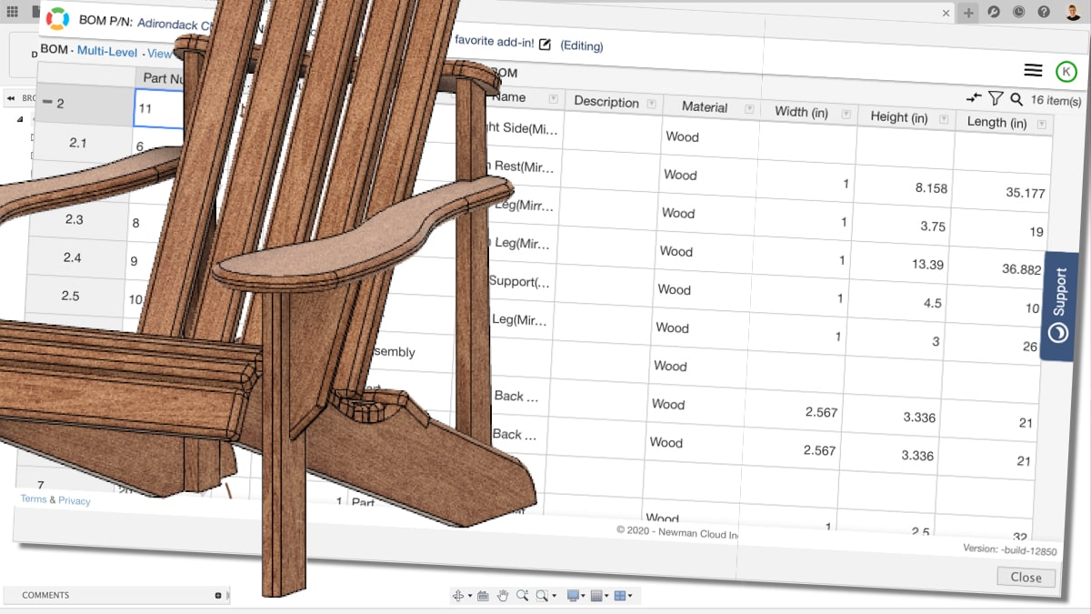
To make this list useful, we first need to ensure our components contain the right information.
Step 1: Add Properties to Your Components
Open the shelf design you saved from the last lesson.
- In the Browser, find your
Shelfcomponent. Right-click it and select Properties.- In the Description field, enter the stock material you would use, for example,
18mm Plywoodor1x6 Pine Board. - Click OK.
- In the Description field, enter the stock material you would use, for example,
- Now, right-click the
Shelfcomponent again and select Physical Material.- In the dialog, find a suitable
Woodmaterial (e.g., Pine, Oak, or just the genericWood) and drag it onto theShelfcomponent in the Browser or viewport.
- In the dialog, find a suitable
- Repeat this process for the
Bracketcomponent.- Properties: Add a Description like
3D Print. - Physical Material: Assign a plastic, such as
ABS PlasticorPETG Plastic. This helps differentiate parts in the list.
- Properties: Add a Description like
These properties will now automatically populate our parts list.
Step 2: Generate the Parts List
The following video provides an excellent walkthrough of creating a parts list in the Drawing workspace. We'll follow this process for our shelf assembly.
Parts List Fusion 360 - Fusion 360 for Woodworkers
Please watch the video 'Parts List Fusion 360' by Product Design Online. It covers the essential steps for generating and customizing a parts list from a 3D assembly, which we will apply to our shelf design.
Watch the sections from 02:59 to 14:08. Focus on how to: Create a new drawing from your design. Insert a parts list table. Customize the columns (Quantity, Part Name, Description, Material). Update the component properties in the design file and see them reflect in the drawing's parts list.
Step 3: Apply the Workflow to Your Shelf
Now, let's apply those steps to your file:
- With your assembly open, go to
File > New Drawing > From Design. - In the dialog, ensure Full Assembly is selected. For sheet size,
A4or8.5 x 11(Letter) is fine. Click OK. - Place a base view of your assembly onto the sheet. An
Isometricview is often best for this purpose. - Go to the toolbar and select Tables > Table (or just Table depending on your UI version).
- Place the table in a corner of the drawing.
Fusion 360 will automatically generate a parts list. It should show one Shelf and two Bracket components. Double-click the table to edit it and customize the columns as shown in the video. A good setup includes:
ItemQTYPart NameDescriptionMaterial
Step 4: The Hardware List
You'll notice our screws are missing from the list. This is because we only modeled holes for them, not the screws themselves. For complex projects, you would model or import standard hardware from a library like McMaster-Carr (a topic we'll cover in the capstone project).
For this project, we can simply add a manual note.
- In the Drawing workspace toolbar, select Text.
- Create a text box on your drawing.
- Add your hardware list, for example:
Hardware Required:
- 4x Countersunk wood screws for wall mounting (e.g., #8 x 1.5")
- 2x Pan-head wood screws to secure shelf (e.g., #8 x 0.75")
Step 5: Finalize the Plan
You now have a drawing sheet that contains a 3D view of your project, an itemized parts list, and a hardware list. This is your manufacturing document. You can save it within Fusion 360 and also export it as a PDF via the Export > Export PDF option for easy printing and viewing in your workshop.
3. Exporting the STL File for 3D Printing
With the plan for the wood and hardware complete, the final step is to generate the file for your 3D printer. The standard file format for this is STL (stereolithography), which describes the model's surface geometry as a mesh of triangles.
The video below clearly explains how to export an STL file from Fusion 360.
Export STL from Fusion 360 for 3D Printing
This short video, 'Export STL from Fusion 360 for 3D Printing' from the What Make Art channel, will guide you through the process of creating a high-quality STL file from a specific component in your design.
Watch the entire video (it's short!). Pay attention to selecting a specific component for export and the 'Refinement' setting, which controls the quality of the final STL mesh.
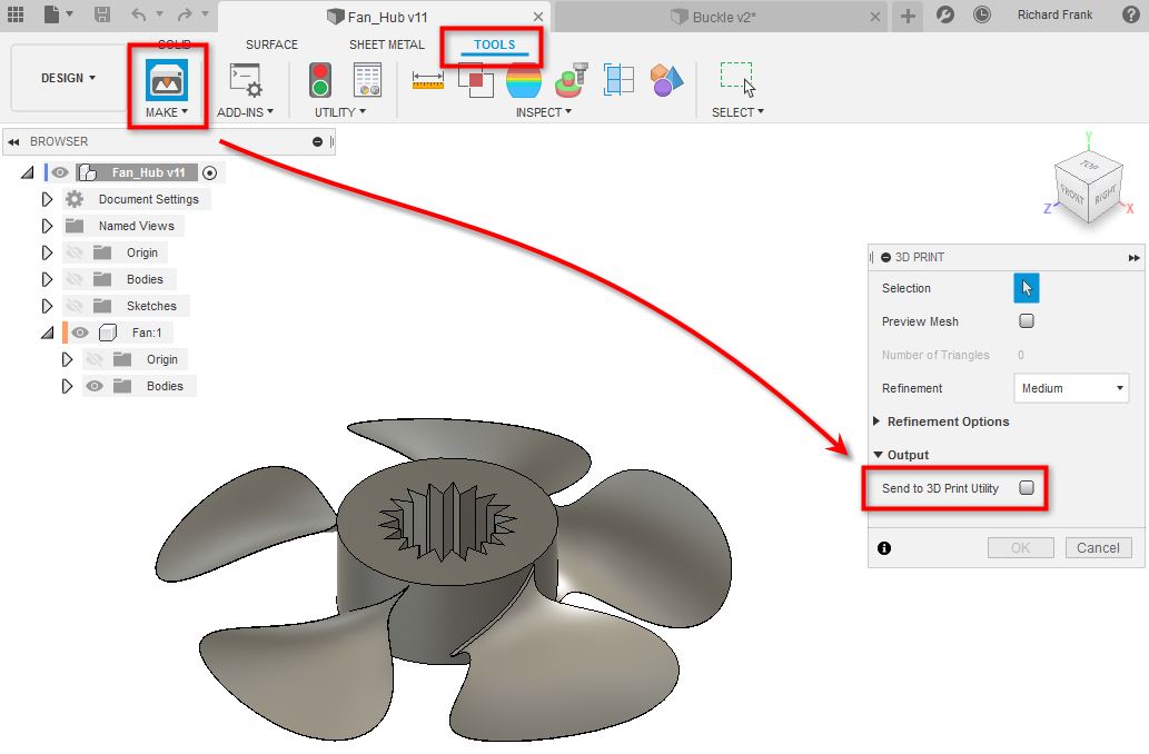
Now, let's export the Bracket component:
- Return to your main Design workspace tab.
- In the Browser, right-click on the
Bracketcomponent. - Select Save as Mesh. (This is a direct way to the same dialog shown in the video).
- In the dialog box:
- Format: STL (Binary)
- Unit Type: Millimeter
- Refinement: High. As the video mentions, modern computers and slicers handle high-polygon files easily, and this ensures your curved surfaces are smooth.
- Click OK and save the STL file to your computer.
Because you created the second bracket using the Copy and Paste commands, it is an identical instance. Therefore, you only need to export one STL file and simply print it twice.
You now have the file ready to be imported into slicer software like Bambu Studio, which we'll cover in a future module.
Conclusion
Excellent work. You have successfully taken a complete 3D assembly and generated a full manufacturing plan. This is the workflow that turns digital ideas into physical realities.
Key Takeaways:
- A comprehensive manufacturing plan includes drawings for traditional fabrication (like woodworking) and digital files for modern methods (like 3D printing).
- The Drawing workspace in Fusion 360 is a powerful tool for creating parts lists, which are automatically generated from the components in your model.
- Populating component Properties (like Description and Physical Material) is key to creating a rich, informative Bill of Materials.
- STL files are the standard for 3D printing and are exported from Fusion 360 using the Save as Mesh or 3D Print commands.
Next Lesson Preview:
You have now completed the module on designing with mixed materials, culminating in this complete project plan. You're ready to tackle something bigger. In our next module, we will begin your capstone project: Designing and Modeling the PC-Integrated Gaming Desk. We will start by defining its functional requirements and constraints, laying the groundwork for the ambitious build you're aiming for. The skills you've consolidated here will be invaluable.