Hello! Welcome back to the course.
In the last few lessons, we've focused on mastering individual, powerful skills. You've learned to model robust parametric components, and most recently, how to create professional 2D drawings from those models. Now it's time to integrate these skills into a complete project, moving from single parts to a multi-material assembly.
Today's lesson is designed to do just that. The learning outcome is to model a simple mixed-material project, such as a small shelf with 3D printed brackets. We will design and assemble a functional object that combines a wooden element with custom 3D-printed hardware, a core competency for your DIY ambitions. This project will serve as the foundation for our next lesson, where we'll generate a complete manufacturing plan.
1. Project Overview: The Wall Shelf
We will be modeling a simple wall-mounted shelf. This project is a classic example of mixed-material design, where each material is used to its strengths: wood for the broad, flat surface of the shelf, and 3D printed plastic for the custom brackets that join it to the wall.
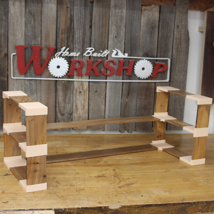
Our final assembly will look something like this, combining standard wood stock with custom-fit printed parts.
Our process will follow a "top-down" design methodology, which is excellent for assemblies:
- Define Project Parameters: We'll start by defining the key dimensions of our entire project.
- Model Components: We will model the shelf and a bracket as separate components within the same design file.
- Create the Assembly: We'll use joints to position the components correctly relative to one another.
2. Setting Up the Parametric Framework
A well-planned project starts with well-planned parameters. This makes the design robust and easy to modify later.
Go to Modify > Change Parameters and create the following User Parameters. Since your BTech was in mechanical engineering, you'll recognize these as the key variables defining our system.
| Parameter Name | Expression (Value) | Comment |
|---|---|---|
shelf_length |
300 mm |
The overall length of the wooden shelf. |
shelf_depth |
120 mm |
The depth of the wooden shelf. |
shelf_thickness |
18 mm |
The thickness of our wood stock. |
bracket_width |
25 mm |
The width (extrusion length) of the bracket. |
bracket_wall_thick |
4 mm |
The wall thickness of the 3D printed part. |
screw_hole_dia |
4.5 mm |
Hole diameter for a standard wood screw. |
fit_tolerance |
0.5 mm |
Clearance for the shelf to fit in the bracket. |
Click OK to save the parameters.
3. Modeling the Components in Place
We'll build our parts as distinct components. This is crucial for creating assemblies and, later, generating a Bill of Materials.
Step 1: Model the Wooden Shelf
- Create a new component by right-clicking the top-level item in the Browser and selecting New Component. Name it
Shelf. Ensure it is activated (the dot is filled). - Create a new sketch on the
XY(top) plane. - Draw a Center Rectangle starting from the origin.
- Dimension its length to
shelf_lengthand its width toshelf_depth. - Finish the sketch and Extrude the profile upwards by
shelf_thickness. - You now have your first component, a simple wooden board.
Step 2: Model the 3D Printed Bracket
This component is more complex. It needs to securely hold the shelf and mount to a wall.
-
Activate the top-level assembly in the Browser.
-
Create another New Component and name it
Bracket. -
We need to sketch the bracket's profile. Create a sketch on the
YZ(right) plane. -
To ensure our bracket fits our shelf, we'll first Project the side profile of the shelf into our sketch.
- Go to
Create > Project/Include > Project. - Select the side face of the shelf and click OK. This will create a purple reference rectangle in your sketch.
- Go to
-
Now, draw the bracket's profile around this reference rectangle.
- Draw an "L" shape that will form the main body of the bracket. The inside corner should be coincident with the bottom-front corner of the projected shelf rectangle.
- Use the Offset tool (
O) to create the outer profile of the bracket. Select the two inner lines of your "L" shape and offset them bybracket_wall_thick. - Close the profile by drawing lines at the ends to create a closed shape.
- Use dimensions and constraints to fully define your sketch. The inner slot for the shelf should be
shelf_depthdeep andshelf_thickness + fit_tolerancehigh. The vertical part of the bracket can be a height of your choosing (e.g., 75mm).
Your sketch should look something like this, with the bracket profile wrapped around the projected shelf profile:
Sketching the bracket profile using the shelf's projected geometry as a reference ensures a perfect fit.
-
Extrude the Bracket:
- Finish the sketch.
- Select the Extrude tool.
- Choose your bracket profile.
- Set the Direction to Symmetric.
- Set the Measurement to Whole Length.
- Set the distance to
bracket_width.
-
Add Mounting Holes:
- Use the Hole tool (
H). - Select the rear face of the bracket (the one that goes against the wall).
- Place two holes. Use sketch points or edge references to position them.
- In the Hole dialog:
- Set Hole Type to Countersink.
- Set the main hole Diameter to
screw_hole_dia. - Set the Countersink Diameter to
screw_hole_dia * 2. - Set Extent to All to ensure it cuts through the part.
- Add a simple (not countersunk) hole on the bottom face of the bracket to secure the shelf. Set its diameter to
screw_hole_dia.
- Use the Hole tool (
-
Add Fillets:
- Add a fillet (
F) to the sharp internal corner of the L-shape. This is crucial for adding strength to a 3D print. A radius ofbracket_wall_thick * 2is a good starting point. - Optionally, add smaller fillets to the outer edges for a more finished look.
- Add a fillet (
4. Assembling the Shelf
Now we'll bring the parts together.
- Activate the top-level assembly in the Browser. You should see your
Shelfcomponent and yourBracketcomponent. - Ground the Shelf: Right-click the
Shelfcomponent in the browser and select Ground. This fixes it in place, providing a stable reference for the assembly. - Create a Second Bracket: Right-click the
Bracketcomponent in the Browser and select Copy. Then right-click the top-level assembly and select Paste. This creates a second, independent instance of the bracket. Drag it away from the first one. - Apply Joints:
- Go to
Assemble > Joint. - Set Motion Type to Rigid.
- We will join the first bracket to the shelf. For Component 1, select the middle of the top inside edge of the bracket's slot. For Component 2, select the middle of the bottom front edge of the shelf. This will snap the bracket into place. Add an offset of
-50 mmon the X-axis (or another suitable value) to position it. - Repeat the process for the second bracket, using an offset of
50 mm.
- Go to
You should now have a fully assembled shelf, with both brackets properly positioned.
The final assembly in Fusion 360, with the shelf and two brackets joined together using Rigid Joints.
5. Verification: The Power of the Parametric Assembly
Test the parametric link. Go back to Modify > Change Parameters and change shelf_depth from 120 mm to 150 mm. Click OK.
Observe how the wooden shelf gets deeper, and critically, the slot in both brackets also gets deeper to match. This is the power of designing components in the context of an assembly and using shared parameters.
Conclusion
Congratulations! You have successfully modeled a complete mixed-material project. You've combined your skills in sketching, solid modeling, parametric design, and assembly to create a functional object from the ground up.
Key Takeaways:
- Top-Down Design: Starting with parameters and building components "in-place" is a powerful workflow for assemblies.
- Component-Based Modeling: Using distinct components is essential for creating assemblies, managing parts, and preparing for manufacturing.
- Contextual Design: Projecting geometry from one component into another's sketch creates intelligent links that automatically update.
- Assembly with Joints: Joints define the spatial relationships between components to form a complete product.
Next Lesson Preview:
You now have a complete digital model of your shelf. But a model is not yet a plan. In our next lesson, we will build directly on this design to generate a complete manufacturing plan. This will include creating a cut list for the wood, a hardware list, and exporting the bracket's STL file for 3D printing—everything you need to take your design from the screen to your workshop. Be sure to save your design.