Hello! Welcome back to our module on designing with mixed materials.
In our last lesson, we focused on the crucial concept of tolerance, designing a U-shaped bracket that could achieve a specific fit on a piece of wood by parametrically controlling the clearance. You learned how to make parts fit together correctly.
Today, we'll build on that by designing a complete, functional 3D printed bracket for joining wood components. We'll move beyond just achieving a fit and incorporate design features for strength, printability, and the use of standard hardware. This is a core skill for your DIY ambitions, as almost any furniture project, including your future gaming desk, will rely on strong, well-designed connectors.
1. The Anatomy of a Functional Bracket
A simple L-bracket might seem trivial, but a good one, especially when 3D printed, requires careful thought. Beyond just its basic shape, we need to consider how it will handle real-world forces and how it will be manufactured.
Strength and Printability
Because FDM 3D prints are built in layers, they are anisotropically strong—meaning they are significantly weaker in tension along the Z-axis (pulling the layers apart) than along the X/Y plane. A simple, sharp 90-degree corner on a bracket creates a major stress concentration point that aligns perfectly with this weakness.
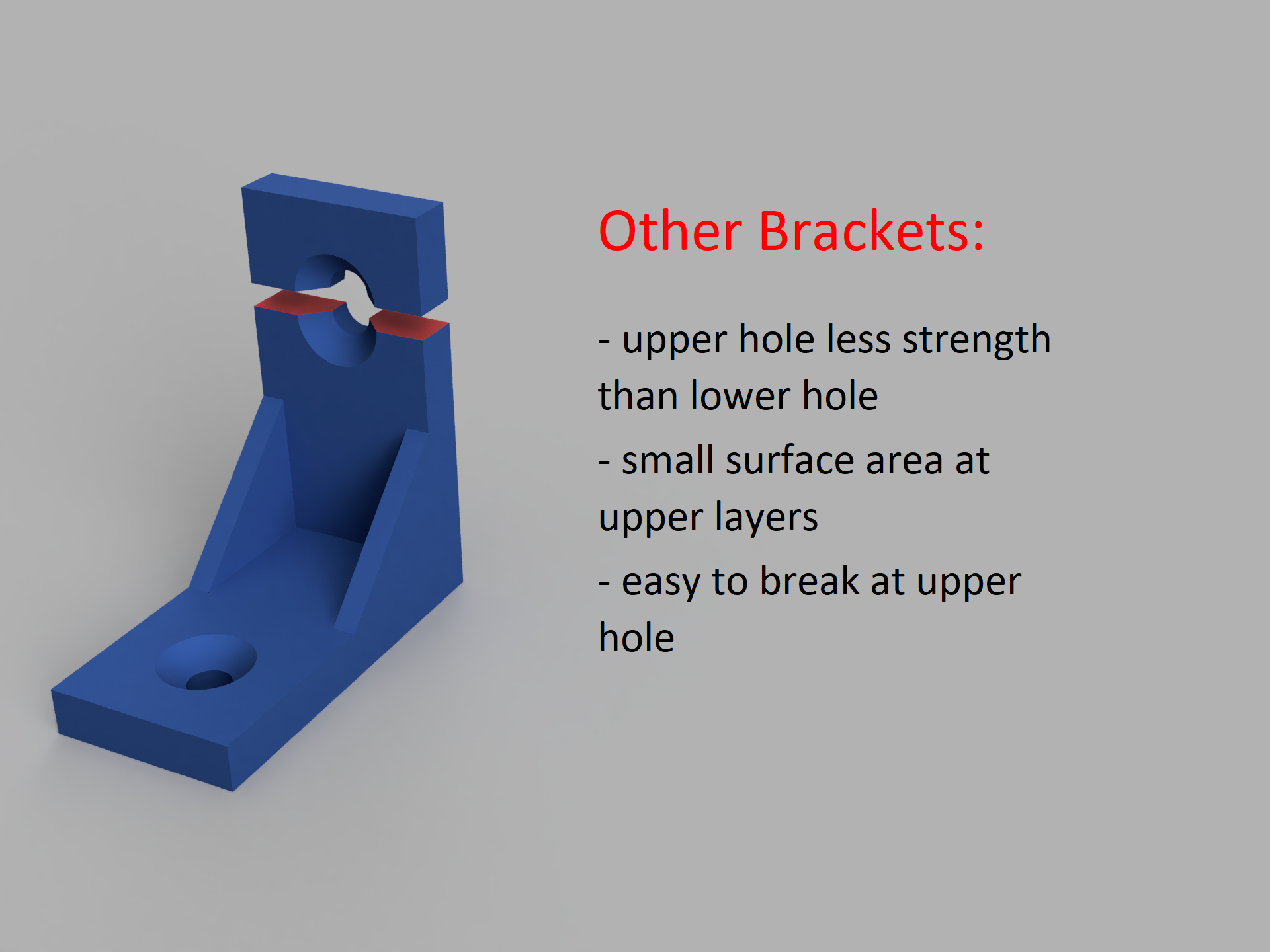
To counteract this, we can add material strategically:
- Fillets: Rounding sharp internal corners distributes stress over a larger area, preventing cracks from starting.
- Gussets (or Ribs): Adding a diagonal support transforms the weak corner into a much stronger triangular structure, effectively bracing it against bending forces.
Designing for Fasteners
How you attach the bracket to the wood is just as important as the bracket's own strength. The type of screw you plan to use dictates the type of hole you should design.

In Fusion 360, it's best to use the dedicated Hole tool (Create > Hole) for this. It allows you to parametrically define simple, counterbore, and countersink holes without needing to sketch and extrude multiple circles.
2. Guided Design: A Parametric 90-Degree Bracket
Let's now design a robust, reusable 90-degree bracket. We will use a video tutorial as a guide for the modeling process, but we will enhance it by applying our knowledge of parametric design and hole features more formally.
3D Printed 90 Degree Angle Bracket with Parametric Features in Fusion 360 Tutorial
The video '3D Printed 90 Degree Angle Bracket' by What Make Art provides an excellent walkthrough of creating a simple but strong bracket. We will follow its process and then refine it.
Please watch the entire video (it's about 5 minutes long). Pay close attention to two key stages: The initial creation of the L-shape from a sketch (0:00-03:06). The addition of the triangular gusset for strength (03:06-05:11).
Now, let's create our own version in Fusion 360, integrating the best practices we've discussed.
Your Task: Model a Robust Bracket (Approx. 30 minutes)
-
Set Up Parameters:
Before you start, open theModify > Change Parametersdialog. Create a set of user parameters to drive the design. This makes it incredibly easy to adapt the bracket for different wood sizes or screw types later.wood_A_thickness = 18mmwood_B_thickness = 18mmbracket_width = 30mmbracket_thickness = 4mmhole_diameter = 4.5mm(for an M4 screw)countersink_diameter = 8mm
-
Sketch the Base and Wall:
- Create a new component named "90-Degree-Bracket".
- On the ground plane (XY), create a sketch for the base of the L-bracket. Instead of one rectangle, sketch two adjoining rectangles.
- One rectangle dimensioned
bracket_widthbywood_A_thickness. - An adjoining rectangle dimensioned
bracket_thicknessby (wood_A_thickness+bracket_thickness).
- One rectangle dimensioned
- This approach lets you define the "footprint" that sits on the wood and the base of the vertical wall in one sketch.
-
Extrude the L-Shape:
- Extrude the base rectangle up by
bracket_thickness. - Show the sketch again. Extrude the profile for the vertical wall up by
wood_B_thickness. Ensure the operation is set to Join.
- Extrude the base rectangle up by
-
Add Strength (Gusset and Fillets):
- Replicate the technique shown in the video (starting at 03:06) to add a gusset. Create a sketch on the center plane of the bracket, draw a line to define the triangle, and extrude it symmetrically with a thickness of
bracket_thickness. - Use the Fillet tool (
Modify > Fillet) to round the sharp internal corner where the two faces of the L-bracket meet. A fillet with a radius equal tobracket_thicknessis often a good starting point. This is a critical step for distributing stress.
- Replicate the technique shown in the video (starting at 03:06) to add a gusset. Create a sketch on the center plane of the bracket, draw a line to define the triangle, and extrude it symmetrically with a thickness of
-
Create the Holes:
- This is where we will improve upon the video's method. Instead of sketching circles, use the Hole tool (
Create > Hole). - Select the face where you want the first hole. You can drag the hole to a preliminary position.
- In the Hole dialog box:
- Set the Hole Type to Countersink.
- Set the Depth to "All".
- Input your parameters:
countersink_diameterfor the top width, andhole_diameterfor the main hole diameter.
- Use the "Reference" options in the dialog to dimension the hole's position precisely from two edges of the bracket face.
- Repeat the process for the other face of the bracket.
- This is where we will improve upon the video's method. Instead of sketching circles, use the Hole tool (
Your final bracket should be a strong, parametrically-driven component ready for any project. Changing wood_A_thickness or hole_diameter in the parameters list should now automatically and correctly update your model.
3. Alternative Design: The Slotted Bracket
The L-bracket is perfect for fastening to the surface of wood. Another common scenario is joining panels at a corner, where you might want the bracket to capture the wood. For this, a slotted bracket is an excellent design pattern.
3D Printable Adjustable Angle Bracket in Fusion 360
The article '3D Printable Adjustable Angle Bracket in Fusion 360' from What Make Art describes how to create a bracket that uses slots to hold wood panels. It also introduces the powerful idea of making the angle itself a parameter.
You don't need to follow this as a full tutorial right now, but skim through the process described in the transcript, starting from 'The first thing I want to do is modify some user parameters'. Notice how a 'ply' parameter is used for the wood thickness, and how the initial sketch creates a channel for the wood to sit in. This is where the clearance we practiced in the last lesson would be applied (slot_width = ply + clearance).
The key difference is in the initial sketch. Instead of an 'L' profile, you create a 'U' profile that defines the slot. You then apply the tolerance principles from our previous lesson to the width of this slot to ensure the wood panel fits perfectly. This design is extremely useful for assembling boxes, cases, or shelving units.
Conclusion
Great work today. You've successfully designed a functional, ready-to-print component that intelligently combines sketching, 3D modeling, and design-for-manufacturing principles.
Key Takeaways:
- Design for Strength: In 3D printing, always reinforce sharp internal corners with fillets and consider adding gussets to L-brackets to counteract layer line weakness.
- Design for Hardware: Use the Hole tool to create features like countersinks and counterbores that match your chosen fasteners.
- Leverage Design Patterns: An L-bracket is great for surface mounting, while a slotted bracket is ideal for capturing panels. Knowing which to use is part of effective design.
- Parametric Design is Key: By driving your bracket's dimensions with parameters, you've created a reusable digital asset, not just a one-off model.
Next Lesson Preview:
Now that you've created a solid 3D model, what's next? Often, you need to communicate your design to others, or create a plan for cutting the wooden parts that will interface with your bracket. In the next lesson, we will navigate the Drawing workspace in Fusion 360 to create a dimensioned orthographic view of a component, turning your 3D model into a professional 2D technical drawing.