Hello! Welcome back to our module on designing with mixed materials.
In the last lesson, we focused on pure woodworking joinery by modeling a half-lap joint. You learned how to create strong, interlocking connections between wooden parts. We also briefly touched on the concept of tolerances in the context of CNC manufacturing, noting that a perfect digital design doesn't always translate to a perfect physical fit.
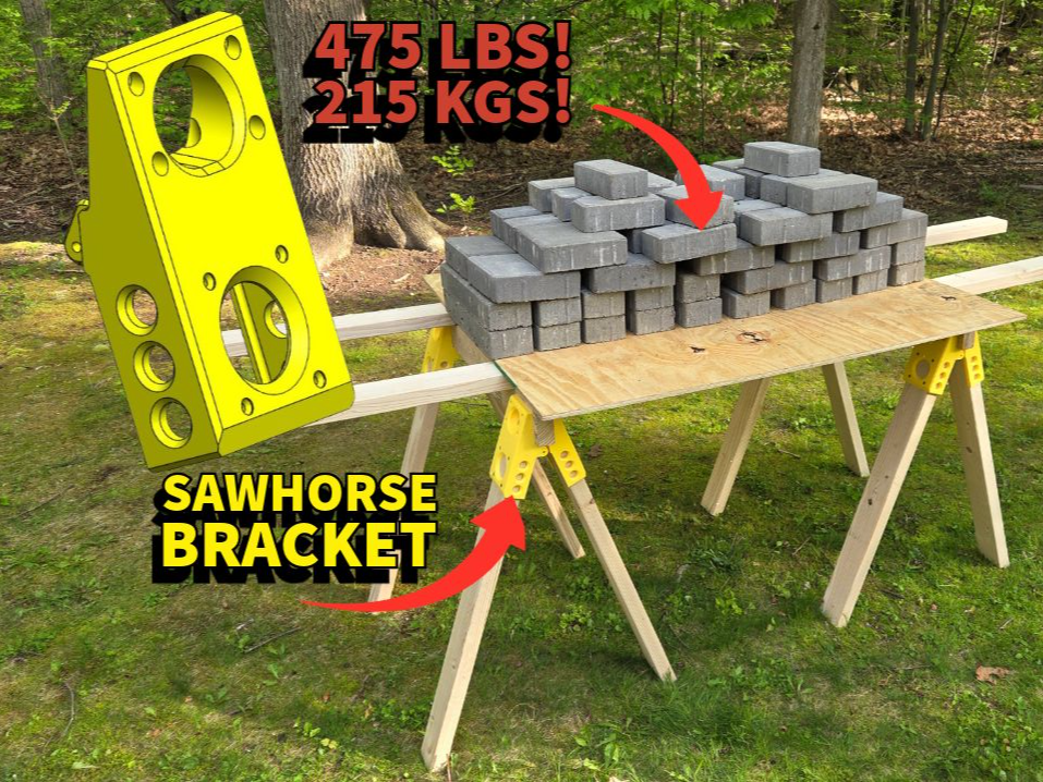
Today, we will dive deep into that concept, focusing specifically on how to apply appropriate tolerances for 3D printed parts that interface with wood. This is a critical skill for your goal of creating custom DIY projects, as it will enable you to design robust brackets, mounts, and connectors that join wooden structures with 3D printed components, like in the frame for your future gaming desk.
1. The Language of Fit: Tolerance and Clearance
Given your mechanical engineering background, you're certainly familiar with the concepts of tolerance and clearance. However, their practical application in Fused Deposition Modeling (FDM) 3D printing has its own specific nuances.
- Tolerance is the unavoidable dimensional variation inherent in a manufacturing process. For a desktop 3D printer, this can be influenced by factors like filament diameter consistency, nozzle wear, material shrinkage, and print speed. A part designed to be 10.0mm wide might print as 10.2mm or 9.9mm.
- Clearance is the intentional space you design between two mating parts to achieve a desired fit.
The video below gives an excellent overview of these concepts specifically for 3D printing.
Beginner's Guide to Fit and Tolerance in Fusion 360 - Get the Perfect Fit from Your 3D Printer / CNC
The video 'Beginner's Guide to Fit and Tolerance in Fusion 360' from Practical Alchemy clearly explains the difference between tolerance and clearance, and why parts designed with exact dimensions often don't fit when 3D printed.
Please watch from the beginning to 04:47. The video uses a simple peg-and-hole example to illustrate how manufacturing variations (tolerance) lead to interference and introduces the concept of 'tolerance stacking'.
2. Types of Fit: From Press-Fit to Slip-Fit
When designing parts that interface, you need to decide how they should behave. Do they need to be permanently pressed together, or should they slide apart easily? This is determined by the clearance, which results in different types of fit.
3D printer accuracy, tolerances and engineering fits between 3D printed parts
The article '3D printer accuracy, tolerances and engineering fits' provides a solid written explanation of the three primary types of engineering fits as they apply to 3D printing.
Please read the section titled '3D printing engineering fits' and its three subsections ('Clearance fit', 'Transition fit', and 'Press fit'). This will solidify your understanding of how to intentionally design for each fit type.
To summarize the key points from the reading:
- Interference Fit (Press-Fit): No clearance, or even a negative clearance (the internal part is designed larger than the external part). The parts must be forced together, creating a strong, semi-permanent bond. Ideal for mounting a bracket you don't intend to remove.
- Transition Fit: A very small clearance. Depending on the actual printed tolerances, the result might be a snug fit that requires a light tap or a loose fit. This is useful for parts that need to be located precisely but might be disassembled later.
- Clearance Fit (Slip-Fit): A larger, defined gap between parts. This allows for free movement, like a pin in a hinge or a part sliding along a track.
3. Finding Your Printer's Sweet Spot
The ideal clearance value isn't universal; it depends on your specific printer (the Bambu A1 you're planning to get), the filament you use, and your slicer settings. The most reliable way to determine your ideal clearances is to design and print a test piece, which aligns perfectly with your preference for hands-on learning.

The video you watched earlier demonstrates how to design a simple version of this. The key is to create a series of slots or holes with progressively larger offsets and a single "master" part to test the fit in each.
Your Goal: To find the values for your machine that correspond to:
- A good press-fit.
- A snug but separable transition fit.
- A smooth, non-wobbly clearance fit.
For a typical, well-calibrated FDM printer, these values often fall in the 0.1mm to 0.5mm range.
4. Applying Tolerances in Fusion 360
Once you know your target clearance values, you need to apply them in your design. When interfacing a 3D print with wood, you'll typically model the wood to its exact dimensions and apply the clearance to the 3D printed part.
The most robust way to do this is with a user parameter, which builds on what you learned in Module 4.
The Best Way to Add Tolerances in Fusion 360!
The video 'The Best Way to Add Tolerances in Fusion 360!' by Joseph Willis shows a fantastic, parametric method for adding tolerance that allows for easy global adjustments.
Please watch from 02:54 to 05:43. Focus on how a user parameter named 'tall' (for tolerance) is created on the fly within the Offset command. See how changing this single parameter updates the entire design instantly. This is the workflow we will use.
5. Practical Exercise: Design a Toleranced Bracket
Let's apply this. We'll design a simple "U" bracket meant to fit over the 18mm thick plywood from our last lesson.
Project Brief:
- Design a 3D printed U-shaped bracket that will slide over an 18mm thick piece of wood.
- The bracket should have a transition fit. Based on common experience, let's start with an assumed clearance of 0.4mm (meaning a 0.2mm gap on each side).
Tasks (Approx. 20 minutes):
- Set up Parameters: In a new design, create user parameters:
wood_thickness = 18mmbracket_clearance = 0.4mmwall_thickness = 3mm(for the bracket itself)
- Model the "Wood": Create a simple block representing the wood. Make it a new component named "Wood" and give it the
wood_thicknessdimension. (e.g., 100mm x 50mm x 18mm). - Create the Bracket Component: Create a new, empty component named "Bracket".
- Sketch the Bracket Profile:
- Create a sketch on a plane that is co-planar with the end-face of the wood block.
- Project the geometry of the wood's cross-section into your sketch (Shortcut:
P). - Use the
Offsettool on the projected lines. For the offset distance, enter the expression:bracket_clearance / 2. This creates the inner wall of your bracket. - Use the
Offsettool again on this newly created inner wall. For the distance, enterwall_thickness. This creates the outer wall. - Close the profile to create a "U" shape.
- Extrude the Bracket: Extrude your "U" shaped profile to create the bracket body.
- Verify and Experiment: Use the
Inspect > Section Analysistool to look at the cross-section. You should see a small, uniform gap between the wood and the bracket. Now, go toModify > Change Parametersand changebracket_clearanceto0.1mm(for a press-fit) or1.0mm(for a loose fit) and watch your model update automatically.
This workflow is the foundation for creating any part that needs to fit precisely with another.
6. A Special Case: Tolerances for Threads
Threads are another common feature where tolerances are critical. A bolt and nut designed with the exact same thread profile will not fit when 3D printed. You must add clearance.
3D Printed Threads – Model Them in Fusion 360
For a deeper look into this specific application, the article '3D Printed Threads' from Product Design Online explains the process.
Please read the sections 'Creating Clearance in Fusion 360' and 'Clearance vs Tolerance'. Note the use of the Offset Face command (shortcut 'Q') to add clearance directly to the thread flanks.
The key takeaway is that for threads, you often apply a negative offset to the thread faces themselves. A starting value of -0.1mm to -0.2mm is common. The article also provides a great practical tip: using a tap and die set to "clean up" printed threads can help achieve a perfect fit.
Conclusion
Excellent work today. You've bridged a critical gap between digital design and physical reality. Understanding and applying tolerances is what separates a model that just looks right on screen from a functional part that works right in your hands.
Key Takeaways:
- Tolerance vs. Clearance: Tolerance is the machine's error; clearance is your intentional design gap.
- The Three Fits: You can design for an Interference (press), Transition, or Clearance (slip) fit by controlling the amount of clearance.
- Test, Don't Guess: The best way to find the right clearances for your printer is to design, print, and measure a tolerance test piece.
- Parametric Tolerances: Using user parameters in Fusion 360 (e.g., in the
Offsetcommand) is the most efficient and flexible way to manage clearances in your designs.
Next Lesson Preview:
In our next lesson, you'll put this all together. We will design a complete 3D printed bracket to join wood components. You'll take the principles from today's exercise and apply them to create a functional, ready-to-print part that solves a real-world connection problem.