Hello! Welcome back to our module on Interrupts and Exception Handling.
In the previous lesson, we established the "what" and "why" of the ARM exception model. We saw that external interrupts (IRQs) are managed by a critical piece of hardware called the Nested Vectored Interrupt Controller (NVIC) and that the processor performs an automatic context switch to handle them.
This lesson directly follows up on that introduction and addresses the learning outcome: Explain the architecture and configuration of the Nested Vectored InterruptController (NVIC). We will dissect the NVIC to understand its components and, most importantly, the registers you will use to control its behavior. Mastering the NVIC is a non-negotiable skill for anyone writing low-level drivers, as it's the heart of any event-driven embedded system.
1. The NVIC Architecture: An Overview
The NVIC acts as a centralized gatekeeper or arbitrator for all peripheral interrupts. It receives interrupt requests from peripherals like timers, UARTs, and GPIOs, and decides which ones get passed along to the processor core based on their configuration.

The name "Nested Vectored Interrupt Controller" perfectly describes its function:
- Vectored: As we learned previously, the NVIC provides a unique exception number (or "vector") for each interrupt source. The processor uses this number to look up the correct handler address in the vector table.
- Nested: This is a key feature. The NVIC manages a priority system that allows a more urgent interrupt to preempt (i.e., interrupt) a less urgent, currently running interrupt handler. We will touch upon the configuration of priority here, and dive deep into the strategies for managing nesting and preemption in the next lesson.
2. Configuring the NVIC: The Control Registers
The entire behavior of the NVIC is controlled through a set of memory-mapped registers located in the System Control Space (SCS). As a driver developer, you'll interact with these registers constantly. A solid understanding of them is essential.
Let's start with a comprehensive overview of the key registers.
A Practical guide to ARM Cortex-M Exception Handling
The article 'A Practical guide to ARM Cortex-M Exception Handling' offers a clear, register-by-register breakdown of the NVIC. This is an excellent reference to familiarize yourself with the tools at your disposal.
Please read the subsection titled 'NVIC Registers'. Focus on understanding the purpose of the five main register types described: Set-Enable/Clear-Enable (ISER/ICER), Set-Pending/Clear-Pending (ISPR/ICPR), Active Bit (IABR), and Priority (IPR).
To reinforce what you've just read, let's summarize the purpose of these register groups. Each group is an array of 32-bit registers, where each bit or byte corresponds to a specific IRQ number.
-
Interrupt Set-Enable (
NVIC_ISERx) & Clear-Enable (NVIC_ICERx)- Purpose: To enable or disable an interrupt in the NVIC.
- How it works: Writing a
1to bitnof anNVIC_ISERregister enables IRQn. Writing a1to the corresponding bit in anNVIC_ICERregister disables it. ReadingISERtells you which interrupts are currently enabled.
-
Interrupt Set-Pending (
NVIC_ISPRx) & Clear-Pending (NVIC_ICPRx)- Purpose: To manage the "pending" state of an interrupt. An interrupt is pending if the request has been received but the CPU has not yet started executing its handler.
- How it works: You can read
ISPRto see which interrupts are pending. You can write toICPRto clear a pending state, which might be necessary if the condition causing the interrupt has already been handled. Writing toISPRallows you to trigger an interrupt from software, which is extremely useful for testing ISRs.
-
Interrupt Priority Registers (
NVIC_IPRx)- Purpose: To assign a priority level to each interrupt. This is the most important configuration for managing real-time behavior.
- How it works: This is an array of 8-bit registers. Each IRQ has one 8-bit field to define its priority. We'll explore this in detail next.
-
Interrupt Active Bit Registers (
NVIC_IABRx) (Not on Cortex-M0/M0+)- Purpose: To check which interrupt is currently active (i.e., its ISR is running).
- How it works: This is a read-only register bank. If bit
nis1, it means IRQnis currently being serviced.
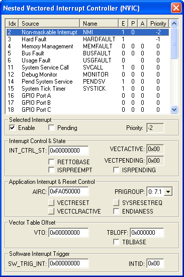
3. A Deep Dive into Priority Configuration
Setting interrupt priorities is fundamental to building a stable and responsive system. There are a few key rules and "gotchas" you must understand.
ARM Cortex-M, Interrupts, and FreeRTOS
The article 'ARM Cortex-M, Interrupts, and FreeRTOS' provides excellent, concise explanations and diagrams for the core concepts of priority configuration.
Please read the sections 'Interrupts Priorities' and 'Priority Bits'. Pay close attention to the counter-intuitive numbering scheme and the concept of left-aligned priority bits.
Let's crystallize those two critical points:
-
Inverted Priority Logic: In the ARM world, a lower numerical value means a higher logical priority (urgency). Priority
0is the highest urgency, priority1is next, and so on. This is a very common source of confusion and a frequent interview question. -
Vendor-Specific, Left-Aligned Priority Bits: Although each interrupt has an 8-bit priority register field, microcontroller vendors only implement a certain number of these bits (e.g., 3 bits for 8 priority levels, or 4 bits for 16 levels). To maintain compatibility, these implemented bits are always the most-significant (left-most) ones. This means that to set a priority level of
3on a system with 4 implemented bits, you don't write0x03. You write0x30.
Test your understanding!
A microcontroller datasheet states it supports 3 priority bits. You want to set an interrupt to the lowest possible priority. What 8-bit hexadecimal value do you write to its NVIC_IPR byte?
Show answer
With 3 priority bits, you have 2³ = 8 levels, from 0 to 7. The lowest priority corresponds to the highest numerical value, which is 7 (0b111). Since the bits are left-aligned in an 8-bit field, you must shift this value. The value to write is 0b11100000, which is 0xE0 in hexadecimal.
4. The Complete Configuration Flow
Enabling an interrupt is a two-part process that involves configuring both the peripheral itself and the NVIC.
ARM Cortex-M, Interrupts, and FreeRTOS
Let's review the standard procedure for enabling an interrupt for a peripheral.
Read the short section 'Interrupts and Devices' which outlines the three-step process for enabling a device interrupt.
The standard sequence is:
- Set Priority (NVIC): Configure the interrupt's priority level in the appropriate
NVIC_IPRregister. It's good practice to do this before enabling the interrupt to avoid it firing with a default priority of 0. - Enable Interrupt (Peripheral): Set the specific bit in the peripheral's own control registers that allows it to generate interrupt requests. For example, a UART peripheral will have a "Receive Interrupt Enable" bit.
- Enable Interrupt (NVIC): Set the corresponding bit in the
NVIC_ISERregister to allow the NVIC to pass the interrupt to the CPU.
Let's see this in action. The following video demonstrates this exact workflow using a high-level configuration tool (STM32CubeMX) and shows the resulting code.
Interrupts on Cortex M - NVIC (demonstrated on STM32) | VIDEO 34
This video provides a practical demonstration of configuring several interrupts on an STM32 microcontroller. It's a great way to see how the register-level concepts we've discussed are applied in a real development environment.
Watch the segment from 16:55 to 24:08. Observe how the presenter enables interrupts for a UART and a Timer. Notice how the tool has settings for enabling the interrupt ('NVIC Settings' tab) and setting its priority, and then look at the generated C code to see the calls to HAL_NVIC_SetPriority() and HAL_NVIC_EnableIRQ(). These HAL functions are simply wrappers around the register writes we've been studying.
Interview Preparation
Being able to clearly articulate how the NVIC works is crucial in an interview for a driver development role.
-
Question: "What are the essential steps to enable a peripheral interrupt, for example, from a UART?"
- Your Answer: "It's a three-step process. First, I would set the interrupt's priority in the NVIC's Interrupt Priority Register (
IPR). Second, I'd configure the UART peripheral itself by setting the relevant interrupt enable bit in its control register—for instance, the 'Receive Interrupt Enable' bit. Finally, I would enable the interrupt in the NVIC by setting its corresponding bit in the Interrupt Set-Enable Register (ISER). All three steps are required."
- Your Answer: "It's a three-step process. First, I would set the interrupt's priority in the NVIC's Interrupt Priority Register (
-
Question: "What is a common pitfall when configuring interrupt priorities on an ARM Cortex-M processor?"
- Your Answer: "A common mistake is forgetting that the priority system is inverted—a lower number means a higher priority. Another is not accounting for the fact that priority bits are left-aligned in the 8-bit
IPRfield. For a system with, say, 4 priority bits, setting the priority to level 5 requires writing0x50, not0x05."
- Your Answer: "A common mistake is forgetting that the priority system is inverted—a lower number means a higher priority. Another is not accounting for the fact that priority bits are left-aligned in the 8-bit
-
Question: "How would you trigger an interrupt from software for testing purposes, and why would you do that?"
- Your Answer: "You can trigger any peripheral interrupt in software by writing a
1to its corresponding bit in the NVIC's Interrupt Set-Pending Register (ISPR). This is incredibly useful for unit testing an Interrupt Service Routine in isolation, without having to set up the physical hardware conditions to make the peripheral generate the interrupt."
- Your Answer: "You can trigger any peripheral interrupt in software by writing a
Conclusion
In this lesson, we've pulled back the curtain on the NVIC. You now understand its architecture and, more importantly, the specific registers used to configure it.
Key Takeaways:
- The NVIC is the central controller for all external (peripheral) interrupts.
- Its behavior is governed by several key register sets:
ISER/ICER(enabling),ISPR/ICPR(pending status), andIPR(priority). - Enabling an interrupt is a multi-step process involving both the peripheral and the NVIC.
- Priority configuration is critical and has two main quirks: inverted numbering (0 is highest) and left-aligned bits.
Next Lesson Preview:
We've learned how to set priorities. The next logical step is to understand the consequences of those settings. In our next lesson, we will focus on how the NVIC uses your priority configuration to manage preemption, allowing more urgent tasks to interrupt less urgent ones. We will also explore the advanced feature of priority grouping to gain even finer control over real-time behavior.