Hello! Let's dive into the second lesson of our module on Advanced System Optimization.
In our previous lesson, we established a solid theoretical foundation by describing the architecture of a DMA controller. We covered what DMA is, why it's essential for offloading the CPU, and explored its core components like channels, streams, and transfer modes. Given your background in ADAS, you know that managing high-throughput data streams from sensors is a constant challenge, and DMA is the primary hardware tool to solve it.
Today, we will move from theory to practice. This lesson directly addresses the learning outcome: Implement a DMA-driven transfer from a peripheral to memory (e.g., for UART or ADC). We'll walk through the configuration steps and code required to make the DMA controller work for us, moving data from a peripheral's data register into a memory buffer, all without CPU intervention.
1. The DMA Configuration Workflow
Before diving into specific peripherals, let's establish a generic workflow for setting up a peripheral-to-memory DMA transfer. This "algorithm" applies to most microcontrollers and provides a mental model for approaching the task.
The process involves configuring three distinct components: the requesting peripheral, the DMA channel, and the interrupt controller (if you need notifications).
- Peripheral Configuration: The peripheral (e.g., ADC, UART) must be configured to generate a DMA request when an event occurs. For a peripheral-to-memory transfer, this event is typically "new data available."
- DMA Channel Configuration: This is the core of the setup. You need to tell the DMA channel everything about the transfer. This configuration is often stored in a descriptor structure in memory.
- Source Address: The address of the peripheral's data register. Since you always read from the same register, the address is fixed, and source address increment must be disabled.
- Destination Address: The starting address of your buffer in RAM. Since you want to fill the buffer, destination address increment must be enabled.
- Transfer Data Size: The size of each individual transfer (e.g., byte for UART, half-word for a 12-bit ADC).
- Transfer Count: The total number of data units to transfer before the DMA operation is considered complete.
- Interrupt Configuration: The DMA controller can trigger an interrupt upon completion of the transfer (or at the halfway point in circular mode). Your application can use this interrupt to know when the data in the buffer is ready for processing.
- Activation: Once everything is configured, you enable the DMA channel and trigger the peripheral to start the process.
The application note "Direct Memory Access" provides a clear, vendor-agnostic overview of this process. While the examples are for EFM32, the core concepts of channel descriptors and register configurations are universal.
Read the 'Introduction' and 'DMA Channel Configuration' sections (pages 2-5). Focus on understanding the role of the DMA descriptors which hold the source/destination addresses, size, and length. This will solidify the general workflow described above.
2. Practical Implementation: ADC to Memory with DMA
Let's apply this workflow to a classic example: continuously sampling an analog sensor with an ADC and storing the results in a buffer. Doing this with the CPU (polling or interrupts) for every single sample is inefficient. DMA is the perfect solution.
We will use DMA in Circular Mode for this. As we discussed in the last lesson, this mode automatically restarts the transfer from the beginning of the buffer once it's full, making it ideal for continuous data acquisition.
Getting Started With STM32 & Nucleo Part 4: Working with ADC and DMA - Maker.io
This video from DigiKey provides an excellent practical demonstration of configuring an ADC with DMA on an STM32 microcontroller using the STM32CubeIDE. It clearly contrasts the inefficient polling method with the highly efficient DMA approach.
First, watch from the beginning to 04:01 to see the problem with CPU-based polling. Then, watch from 10:05 to 14:24. This second segment shows the complete DMA implementation. Pay close attention to: The ADC configuration for Continuous Conversion Mode. The DMA configuration for Circular Mode. Setting the memory address to increment while the peripheral address does not. The use of the HAL_ADC_ConvHalfCpltCallback() and HAL_ADC_ConvCpltCallback() functions to implement a ping-pong buffer, allowing the CPU to process one half of the buffer while the DMA fills the other.
This "ping-pong" buffering technique shown in the video is a powerful design pattern. It minimizes the chance of data being overwritten by the DMA while the CPU is processing it, making the system robust. You can imagine one buffer for the RADAR's current scan while the application processes the data from the previous scan in another buffer.
Test your understanding!
You are tasked with capturing 1024 samples from a 10-bit ADC into a buffer. The MCU is 32-bit.
- What data type would you choose for your destination buffer in C (
uint8_t,uint16_t, oruint32_t) and why? - What would you configure as the source and destination data width/size in the DMA controller settings?
Show answer
- You should use a
uint16_tarray for the destination buffer. A 10-bit ADC value requires more than 8 bits (uint8_t), souint16_t(a half-word) is the next smallest standard C data type that can hold it. Usinguint32_twould waste memory. - You would configure both the source and destination data width to Half-Word (16 bits). The source is the ADC's data register, which provides the 10-bit value (typically right-aligned in a 16-bit register). The destination is the
uint16_tbuffer. The DMA will perform 16-bit to 16-bit transfers.
3. Practical Implementation: UART to Memory with DMA
Another common use case is receiving data over a UART. While you can use DMA to transmit data (memory-to-peripheral), using it for reception (peripheral-to-memory) is more complex but also more beneficial, as it allows your application to handle incoming data streams without blocking or intensive interrupt handling.
STM32 UART #2: Efficient Data Transmission Using Interrupts & DMA
This video from ControllersTech focuses on UART transmission with DMA, but the configuration principles and HAL functions are very similar for reception. It provides a great visual walkthrough of the CubeMX setup and the difference between Normal and Circular modes.
Watch from 07:06 to 12:22. While this demonstrates HAL_UART_Transmit_DMA, notice the use of HAL_UART_TxCpltCallback() and the discussion of Normal vs. Circular mode. For reception, you would use HAL_UART_Receive_DMA and the HAL_UART_RxCpltCallback. The core logic of starting a transfer and waiting for the callback remains the same.
For robustly handling UART data of unknown length, a common and powerful technique is to combine a DMA in circular mode with a software-managed ring (or circular) buffer.
Here's how it works:
- The DMA is configured in circular mode to continuously write incoming UART bytes into a large hardware buffer.
- The DMA controller automatically wraps the write pointer around to the start of the buffer when it reaches the end.
- Your application software maintains a
read_pointerthat tracks how far it has processed the data in the buffer. - The DMA's
write_pointer(which can be read from a DMA register) is always ahead of or at the same position as your software'sread_pointer. - The amount of unread data is the difference between the DMA's current write position and your software's read position. Your application can then process this data at its own pace.
This decouples the real-time data arrival from the application's processing time, which is exactly the kind of robust design required in automotive systems.
4. Advanced Topic: DMA and Cache Coherency
Now for a critical topic that separates junior from senior embedded engineers, and one you'll appreciate from your system-level work. On modern ARM Cortex-A/R processors with data caches (D-Cache), using DMA can introduce subtle and frustrating bugs if you're not careful. This is a prime interview question for an advanced role.
The Problem:
- The DMA controller receives data from a peripheral (e.g., Ethernet) and writes it directly to a buffer in RAM.
- The CPU's data cache might already contain an older, "stale" version of the data for that same memory address.
- When your application code tries to read the new data from the buffer, the CPU performs a cache hit and reads the stale data from its cache, ignoring the fresh data that the DMA wrote to RAM. The CPU is completely unaware that the underlying memory has been changed by another bus master (the DMA).
The Solution: Cache Maintenance
You must explicitly tell the CPU that a region of memory has been modified externally. Before your CPU reads from the DMA buffer, you must perform a cache invalidate operation on that memory region.
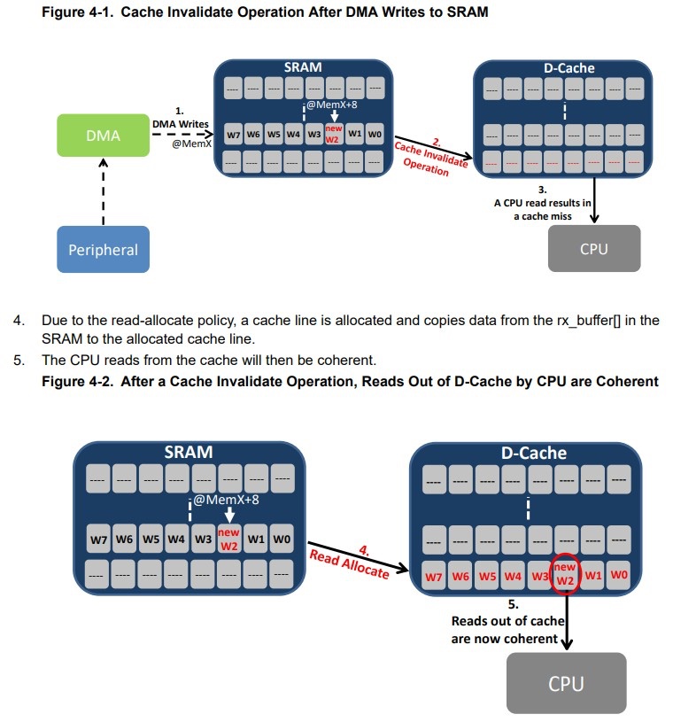
In practice, this means calling a specific function or using an assembly instruction right after your DMA transfer-complete interrupt fires, but before your application logic accesses the buffer. For STM32 HAL, this might look something like SCB_InvalidateDCache_by_Addr((uint32_t*)buffer, size);.
Forgetting this step can lead to your application processing old or corrupted data, a bug that is notoriously difficult to debug because it's timing-dependent and disappears if you try to step through with a debugger (as debugging often flushes or disables caches).
Conclusion
In this lesson, we transitioned from DMA theory to hands-on implementation. We've established a clear workflow for configuring DMA and applied it to two common peripherals, the ADC and UART. Most importantly, we've explored the critical advanced topic of cache coherency, a key consideration for robust driver development on high-performance MCUs.
Key Takeaways:
- DMA Configuration is a 3-step process: Configure the peripheral, configure the DMA channel (source/dest address, size, count, mode), and configure interrupts.
- For peripheral-to-memory transfers, the source address (peripheral register) is fixed, and the destination address (memory buffer) is incremented.
- Circular Mode is extremely useful for continuous data streams, and when combined with half/full transfer callbacks, enables efficient ping-pong buffering.
- For robustly handling variable-length incoming data (like from a UART), a DMA in circular mode paired with a software ring buffer is a superior design.
- Crucial Interview Point: On processors with a data cache, you must perform a cache invalidate operation on the DMA buffer before the CPU accesses it to ensure cache coherency.
Interview Preparation:
- Question: "Walk me through the high-level steps to configure DMA to continuously read data from an ADC into a memory buffer."
- Your Answer: "First, I'd configure the ADC for continuous conversion mode and enable its DMA request signal. Then, I'd configure a DMA channel in circular mode. The source would be the ADC's data register with address increment disabled. The destination would be the start of my RAM buffer with address increment enabled. I'd set the data width to match the ADC resolution (e.g., half-word). Finally, I would enable DMA interrupts for half-transfer and full-transfer complete. In those ISRs, I'd signal the main application to process the respective half of the buffer, implementing a ping-pong scheme. After the ISR signals the CPU, and before processing, I would perform a cache invalidate operation on the buffer region to ensure data coherency."
- Question: "Your application is processing corrupted data from a DMA buffer. What's a likely cause on a system with an ARM Cortex-A9 core?"
- Your Answer: "Given a Cortex-A9 core, which has a data cache, the most likely cause is a cache coherency issue. The DMA writes to RAM, but the CPU is reading stale data from its cache. The solution is to perform a cache invalidate operation on the memory range of the DMA buffer after the DMA transfer is complete but before the CPU attempts to read from it."
Next Lesson Preview:
We now have the skills to move data efficiently from a peripheral to memory. In the next lesson, we will tackle a more complex peripheral: "Integrate DMA with an SPI driver to enable high-throughput, non-blocking data transfers." This will require us to manage two DMA channels simultaneously (one for transmitting and one for receiving), building directly on the concepts we've learned today.