Hello! Welcome to the next lesson in your preparation for advanced embedded driver development roles.
In our last session, we delved into the ARM TrustZone architecture and saw how to use a Secure Monitor Call (SMC) to create a gateway between the Normal and Secure worlds. We've established a secure environment, but a critical question remains: how can we be certain that the software running in any world—secure or otherwise—is the authentic, untampered code created by the developer?
This lesson addresses that question directly. Your learning outcome is to explain the principles of a secure boot process and chain of trust. We will explore how a device, from the very first instruction it executes at power-on, can build a verifiable chain of software components, ensuring system integrity. This concept is the bedrock of security in modern embedded systems, especially in the automotive domain where your experience lies.
1. The Goal of Secure Boot
The primary goal of a secure boot process is straightforward: to prevent the execution of unauthorized or malicious software. In an automotive ECU, this is paramount. An attacker who could replace the standard firmware with their own could compromise vehicle safety, steal data, or alter the vehicle's function.
The fundamental principle is to measure and verify each piece of software before it is executed. A trusted component checks the next component in the boot sequence against an expected value. If the check passes, that component is executed and becomes the new trusted component, responsible for verifying the next stage.
How to secure automotive ECUs -- introducing HSM technology and trusted boot feature
To start, let's watch a segment that defines the goal of trusted boot and introduces the core principle of verifying code before execution. This video frames the discussion in a practical context.
Watch the segment from 22:00 to 24:35. Focus on the definition of the ultimate goal and the explanation of how code is 'measured' by a trusted component and compared to an expected result.
This sequential verification process creates what is known as a Chain of Trust.
2. The Chain of Trust: How it Works
The chain of trust is the core concept of secure boot. Imagine a chain where each link is a piece of software (e.g., a bootloader, an OS kernel). For the chain to be strong, each link must be verified by the previous one before it's added. If any link is found to be fraudulent, the chain is broken, and the boot process is halted.
Secure Boot from A to Z - Quentin Schulz & Mylène Josserand, Bootlin (formerly Free Electrons)
The following video provides an excellent introduction to the chain of trust concept and differentiates the cryptographic methods used.
Please watch from 00:51 to 07:55. Pay close attention to: The explanation of how the first element authenticates the second, the second authenticates the third, and so on. The critical distinction between digital signature verification (for authenticity and integrity) and encryption (for confidentiality).
As the video highlighted, secure boot relies on asymmetric cryptography and digital signatures, not encryption. The software itself is typically readable, but any modification to it will invalidate its signature.
The process is as follows:
- A developer generates a cryptographic hash (e.g., SHA-256) of the final software binary.
- This hash is then "signed" using a private key. This signature is a small block of data.
- The signature is appended to the binary image.
- On the device, the corresponding public key is stored in a secure, immutable location.
- During boot, the preceding software stage (the verifier) does two things:
- It calculates a fresh hash of the binary image it just loaded.
- It uses the stored public key to decrypt the signature, revealing the original hash calculated by the developer.
- If the freshly calculated hash matches the developer's original hash, the binary is authentic and untampered. The verifier can then transfer execution to it.
3. The Anchor: The Root of Trust
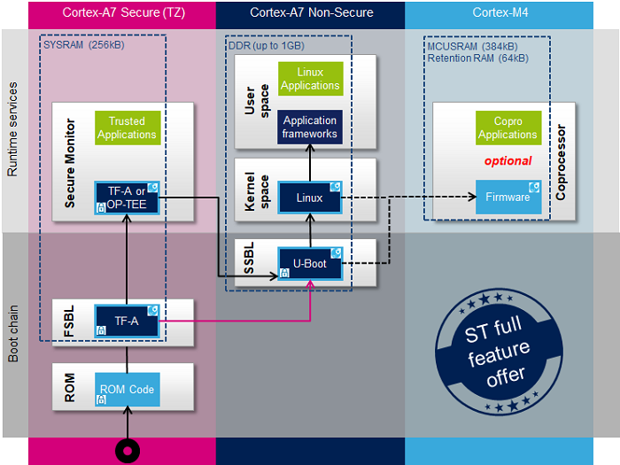
A chain is only as strong as its anchor. The chain of trust must start from a component that is inherently trusted and cannot be modified. This is known as the Hardware Root of Trust (RoT).
In most SoCs, the RoT is a small piece of code permanently etched into the chip's Boot ROM during manufacturing. This code is immutable. Its job is to verify the very first stage of mutable software loaded from flash or other non-volatile memory.
Arm PSA Trusted Boot and Firmware Update Specification
The Arm Platform Security Architecture (PSA) specification provides a formal definition of the chain of trust and the immutable bootloader that acts as its root.
Please read the following two sections: Start with section 3.2 Chain of Trust (informational) to understand the formal description of how the chain begins at reset with a hardware component. Then read section 3.7 Immutable bootloader which details the role of this first piece of code and where it's located (ROM or locked eFlash).
To perform its verification, the Boot ROM needs access to the public key. Storing the entire key in the limited ROM space can be inefficient. A common practice, which your experience with microcontrollers will make intuitive, is to store a hash of the public key in one-time programmable (OTP) fuses on the SoC. The full public key can be stored with the bootloader image in flash. The Boot ROM then reads the public key from flash, hashes it, and compares it to the trusted hash stored in the OTP fuses before using it.
4. The Boot Sequence: A Practical Example
Let's walk through a typical boot sequence in a system using ARM TrustZone, building on what we learned in the last lesson about Trusted Firmware-A (TF-A).
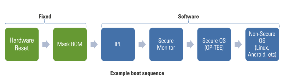
The process, tying into the TF-A terminology, often looks like this:
- Power On -> Boot ROM (BL1): The processor begins executing from the immutable Boot ROM (this is
BL1in the TF-A context). It contains the Root of Trust Public Key (ROTPK) or its hash. It loads the next stage bootloader (BL2) from flash into RAM. - Verification of BL2: The Boot ROM calculates the hash of
BL2and verifies its signature using the ROTPK. If it matches, it jumps toBL2. The chain is now one link long. - BL2 Execution:
BL2is now the trusted verifier. Its job is to load the subsequent images for both the Secure and Normal worlds:BL31: The EL3 Secure Monitor runtime (the core of TF-A).BL32: The Trusted Execution Environment (TEE) or Secure OS.BL33: The Normal World bootloader (e.g., U-Boot).
- Verification of BL3x:
BL2contains the public keys needed to verifyBL31,BL32, andBL33. It authenticates each of them before proceeding. - Execution Handoff: Once verified,
BL2jumps toBL31(the Secure Monitor), passing information about the entry points for the other images.BL31then completes the setup of the Secure World and finally launches the Normal World bootloader (BL33/U-Boot) to boot the main OS like Linux.
This multi-stage process is powerful. As you've seen in automotive development with the V-model, separating concerns is crucial. The silicon vendor (who makes the SoC) provides the Boot ROM (BL1). As a Tier 1 developer, you might provide the next stage (BL2), which then loads a bootloader (BL33/U-Boot) and an OS (Linux) provided by other parties. The chain of trust ensures all these components from different suppliers can be integrated securely.
Security Analysis of TEEs on TrustZone
This document connects the secure boot concept directly to a TrustZone-enabled processor, illustrating the typical BL1/BL2/BL3x flow.
Read the 'Secure Boot' section on page 6. The diagram and accompanying text clearly describe the roles of the different bootloader stages (BL1, BL2, BL31, etc.) in establishing the secure environment.
5. An Important Distinction: Secure Boot vs. Measured Boot
There is a related concept called Measured Boot. It's an important distinction to understand for interviews.
- Secure Boot is about enforcement. If a signature is invalid, the boot process stops. It prevents the system from booting into an untrusted state.
- Measured Boot is about recording and reporting (attestation). During a measured boot, each component's hash is recorded in a secure log (e.g., in a Trusted Platform Module or TPM). The system will still boot, but it creates a verifiable audit trail of the exact software that was loaded. This log can then be sent to a remote server to "attest" to the device's state, proving what software is currently running.
The two are often used together to provide both enforcement and attestation.
Test your understanding!
Imagine your AUTOSAR ECU's bootloader has just been verified by the Boot ROM. The bootloader now needs to load and verify the main AUTOSAR OS/application image. In simple terms, what three steps must the bootloader perform to maintain the chain of trust?
Show answer
- Load: The bootloader loads the entire AUTOSAR OS/application image from flash memory into RAM.
- Verify: It calculates the cryptographic hash of the image in RAM. It then uses its own securely stored public key to verify the digital signature that is appended to the OS image. This confirms the image is authentic and has not been altered.
- Execute: If the verification is successful, the bootloader transfers control by jumping to the entry point of the AUTOSAR OS. If verification fails, it should enter an error state, which might involve logging the failure and safely halting the system.
6. Interview Corner
Q1: Explain the concept of a chain of trust. Where does it start and how is it maintained?
A: The chain of trust is the foundation of secure boot. It's a process where each software component is cryptographically verified before it's allowed to run. It starts with a hardware Root of Trust, which is typically immutable code in the SoC's Boot ROM. This RoT verifies the first-stage bootloader using a public key stored securely in hardware (e.g., in OTP fuses). Once verified, that bootloader becomes the new trusted entity and is responsible for verifying the next stage (like the OS kernel). This continues sequentially, with each verified component extending the chain of trust to the next, until the entire system is booted.
Q2: What is the difference between secure boot and measured boot?
A: Secure boot is an enforcement mechanism; it prevents the system from booting if any component fails signature verification. Its goal is to ensure only trusted code ever runs. Measured boot is a recording mechanism; it calculates a hash of each component as it loads and stores these measurements in a secure log. The system may still boot with untrusted code, but this log can be sent to a remote server to attest to the device's software state, allowing the server to decide if it trusts the device.
Q3: You're designing a secure boot system for an automotive ECU. What is the role of the silicon vendor versus you (the Tier 1 developer) in this process?
A: The roles are distinct and form different parts of the chain. The silicon vendor provides the anchor of the chain: the Hardware Root of Trust. This includes the immutable Boot ROM and the mechanism for securely provisioning the initial public key (or its hash), often via OTP fuses. My role as a Tier 1 developer is to build the next link. I would use the private key corresponding to the public key provisioned by the silicon vendor to sign my bootloader. This bootloader, once verified by the Boot ROM, becomes the trusted entity responsible for loading and verifying the rest of the software stack, such as the AUTOSAR OS, middleware, and application layers, which might come from us or other suppliers.
Conclusion
Today, we've established the critical principles behind ensuring a device starts in a known, trusted state. You've seen that secure boot is not a single action but a sequential process that builds a cryptographic chain of trust from an immutable hardware anchor.
Key Takeaways:
- The goal of secure boot is to prevent unauthorized code execution by verifying each software stage before it runs.
- This is achieved by building a Chain of Trust, where each link verifies the next using digital signatures.
- The process is anchored by an immutable Hardware Root of Trust (RoT), typically in the SoC's Boot ROM.
- The RoT uses a Root of Trust Public Key (ROTPK), often protected by storing its hash in OTP fuses, to verify the first mutable software stage.
- Multi-stage bootloaders (e.g.,
BL1,BL2,BL33) allow for a flexible and secure way to manage software components from different vendors in the supply chain.
Next Lesson Preview:
The entire secure boot process hinges on fast, reliable cryptography and the absolute protection of keys. In our next lesson, we will explore the role of a Hardware Security Module (HSM) and how this dedicated coprocessor is used for high-performance cryptographic operations and secure key storage, making robust security features like secure boot practical in resource-constrained automotive environments.