Hello! Welcome back to our series on advanced embedded driver development.
In our last lesson, we established the "what" and "why" of ARM TrustZone, exploring how it creates hardware-enforced Secure and Non-secure worlds. We learned that the only legitimate way to cross from the Normal World to the Secure World is via a controlled gateway managed by the Secure Monitor at Exception Level 3 (EL3).
Today, we focus on the "how." Your learning goal is to implement a Secure Monitor Call (SMC) to transition between Non-Secure and Secure worlds. We will dissect the SMC instruction, the standardized calling convention that governs it, and the software in EL3 that handles the request and orchestrates the world switch. This is a fundamental skill for anyone working on the secure foundations of an ARM-based system.
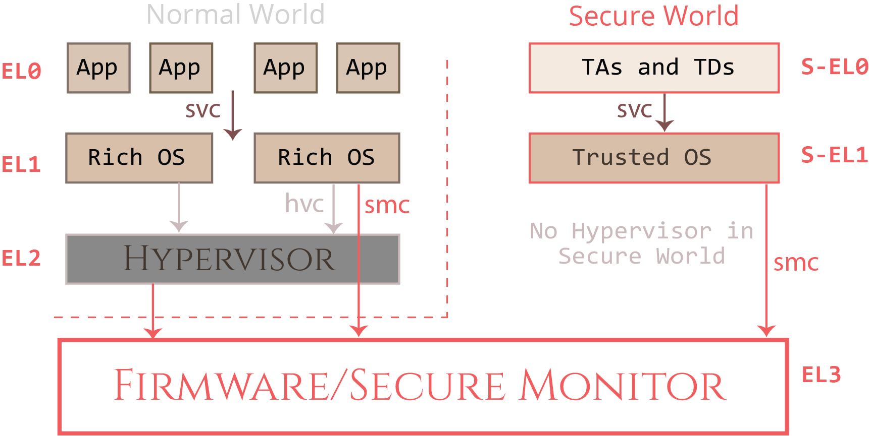
1. The Secure Monitor Call (SMC) as a Standardized API
An SMC is not just an arbitrary jump; it's a synchronous exception that triggers a mode switch to EL3. To ensure interoperability between different software components (e.g., a standard Linux kernel and a proprietary secure firmware), ARM defines the SMC Calling Convention (SMCCC). This convention standardizes how services are requested, how parameters are passed, and how results are returned.
The reference implementation for this architecture on A-class processors is the Trusted Firmware-A (TF-A) project, which provides the EL3 monitor firmware (known as BL31).
Technical Overview of the Trusted Firmware: A Class Open Source Project
To set the stage, let's watch a brief overview of the Trusted Firmware-A project. This will help you understand the context in which a real-world Secure Monitor operates.
Watch the segment from 01:14 to 04:15. Focus on how it describes the relationship between the Normal and Secure worlds and identifies the SMC layer as the communication mechanism. Note the mention of BL31 as the runtime component that handles these calls.
As the video explained, the SMC layer is a well-defined interface. Let's dig into the details of that interface.
EL3 Runtime Service Writer's Guide
The TF-A documentation provides a clear guide for developers who want to write runtime services that are invoked via SMC. We will use it to understand how SMCs are structured and categorized.
Please read the 'Introduction' and 'Owning Entities, Call Types and Function IDs' sections. Pay close attention to the structure of the SMC Function ID and the concept of an Owning Entity Number (OEN). This explains how the system knows whether an SMC is for a standard service like PSCI, a SiP (silicon provider) service, or a Trusted OS.
To summarize the key points from that reading:
- An SMC is initiated by the
smcinstruction. - The
W0(orX0) register holds the SMC Function Identifier (smc_fid). - The
smc_fidis a 32-bit value that encodes:- Call Type (bit 31):
0for Fast Call,1for Yielding/Standard Call. - Calling Convention (bit 30):
0for SMC32 (32-bit args),1for SMC64 (64-bit args). - Owning Entity Number (OEN, bits 23-16): Identifies the service owner (e.g., ARM Architecture, SiP, OEM, Trusted OS).
- Function Number (bits 15-0): The specific function being called within that service.
- Call Type (bit 31):
- Arguments are passed in registers
X1throughX7. - Return values are passed back in
X0throughX7.
This standardized structure allows the Secure Monitor to act as a router, directing incoming requests to the correct service handler.
2. Implementing the SMC Handler in EL3
When an smc instruction is executed in the Normal World (e.g., at EL1), the processor takes a synchronous exception to EL3. The Secure Monitor's exception handler must then perform the following steps:
- Identify the Exception: Read the Exception Syndrome Register (
ESR_EL3) to confirm the cause was an SMC instruction. - Decode the Request: Read the
smc_fidfrom registerX0. - Dispatch to Service: Based on the OEN in the
smc_fid, forward the call to the appropriate registered service handler. - Execute and Return: The service handler performs its function and prepares the return values in registers
X0-X7before returning from the exception.
The following resource shows a simplified assembly implementation of this logic.
This blog post provides a clear, concise assembly code snippet demonstrating how an EL3 monitor handles an incoming SMC.
Read the section 'EL3: The Secure Monitor' and study the associated assembly code snippet. Notice how it reads esr_el3, checks for the SMC exception class (0x17), and then branches to an smc_handler.
In a full-featured firmware like TF-A, this raw assembly logic is wrapped in a C framework. Services register themselves with the monitor during initialization, providing a function pointer to their handler.
EL3 Runtime Service Writer's Guide
Let's revisit the TF-A Writer's Guide to see how this is abstracted in C. This connects the assembly concepts to a practical software framework.
First, skim section 'Registering a runtime service' to see the DECLARE_RT_SVC() macro. Then, read section 'Handling runtime service requests' carefully. This details the responsibilities of the C handler function, such as validating the function ID, checking the caller's security state (is_caller_non_secure(flags)), and using the SMC_RETn() macros to return values.
Your experience with AUTOSAR BSW integration is relevant here. Just as you integrate different modules (e.g., Can, Com, PduR) that register their services with the RTE, here you have different secure services (PSCI, SiP, etc.) that register their SMC handlers with the EL3 runtime framework.
3. Implementing the World Switch
Not all SMCs result in a world switch. A simple request might be handled entirely within EL3. However, if the request is for a complex service provided by a Trusted OS (running at S-EL1), the Secure Monitor must perform a full context switch.
The key to the world switch is the Secure Configuration Register, SCR_EL3. Its NS (Non-Secure) bit determines the security state of the lower exception levels.
SCR_EL3.NS = 1: EL0/1/2 are in the Non-secure state.SCR_EL3.NS = 0: EL0/1/2 are in the Secure state.
The process to switch from Normal to Secure world is:
- Receive the SMC in EL3.
- Save the complete context of the Normal World (GPRs,
SP_ELx,SPSR_ELx,ELR_ELx). - Set up the entry parameters for the Secure World (e.g., in registers
X0-X4). - Modify
SCR_EL3to clear theNSbit (bic x0, x0, #1). - Set
SPSR_EL3to the desired state for entering the Secure World (e.g., target S-EL1). - Set
ELR_EL3to the entry point address in the Secure World. - Execute
eret. The processor resumes atELR_EL3in the new security state.
The same blog post provides another excellent code snippet showing exactly how to modify SCR_EL3 to perform the world switch.
Now read the section 'Security States: Secure vs. Non-secure Worlds' and examine the final code snippet. This shows the critical msr scr_el3, x0 instruction that commits the change in security state.
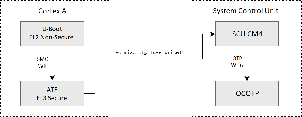
This mechanism is used in many real-world automotive scenarios. For instance, writing to One-Time Programmable (OTP) fuses for configuration or key storage is a highly sensitive operation. A non-secure bootloader like U-Boot would use an SMC to request the ARM Trusted Firmware (ATF) to perform the write.
Test your understanding!
Let's put this together with a small coding exercise. Imagine you need to create a C function that can be called from a non-secure OS driver to request a service from the secure world. The service has an OEN of 50 (Trusted OS call) and a function number of 123. The call is SMC64 and is a fast call. It takes one 64-bit argument.
Write a C function uint64_t call_secure_service(uint64_t arg1) that uses inline assembly to execute the appropriate smc instruction.
Show answer
The smc_fid needs to be constructed first.
- Call Type (Fast):
0 - Calling Convention (SMC64):
1 - OEN:
50(0x32) - Function Number:
123(0x7B)
So, smc_fid is 0x4000327B for SMC64, or 0x0000327B for SMC32. Since the spec says SMC64, we'll use that (0xC000327B if it were a yielding call, 0x8000327B for SMC32 yielding). Let's assume SMC64 Fast Call: 0x4000327B.
Here is the C function with GCC/Clang style inline assembly:
#include <stdint.h>

// Construct the SMC Function ID
// SMC64 Fast Call: Type=0 (bit31), CC=1 (bit30)
// OEN=50 (0x32), Fn_Num=123 (0x7B)
#define SECURE_SERVICE_SMC_FID 0x4000327B

uint64_t call_secure_service(uint64_t arg1) {
    register uint64_t r0 __asm__("x0") = SECURE_SERVICE_SMC_FID;
    register uint64_t r1 __asm__("x1") = arg1;

    // The 'smc #0' instruction is executed. The immediate value is ignored by the CPU
    // but can be used by the handler. Conventionally, it's 0.
    // The registers x0 and x1 are specified as both input and output ('+r').
    __asm__ volatile (
        "smc #0"
        : "+r"(r0), "+r"(r1) // Output operands
        : // Input operands (already specified in output)
        : "x2", "x3", "x4", "x5", "x6", "x7", "memory", "cc" // Clobbered registers
    );

    // The return value from the secure service will be in x0.
    return r0;
}
This demonstrates how high-level code prepares registers according to the SMCCC and then uses an inline smc instruction to trap into the Secure Monitor.
4. A Practical Look at World Transitions (Cortex-M)
While we've focused on Cortex-A's SMC instruction, it's insightful to see the equivalent process on a Cortex-M processor with TrustZone-M. The mechanism is different (SG instruction via "veneer" functions instead of SMC), but the principle of a controlled transition from non-secure to secure code is identical. Watching a debug session can make these abstract concepts very concrete.
6 TrustZone and secure hello world
This video demonstrates a 'hello world' project with separate secure and non-secure parts on a Cortex-M33. It shows how the non-secure code calls a function implemented in the secure world and lets you visualize the transition during a debug session.
Watch the two segments: (07:57 - 10:15): This part shows how the non-secure project calls a function (printf_non_secure_entry) that is defined in the secure project, using a 'veneer table' as the gateway. (10:15 - 13:15): This shows the debugging process. Observe how the program counter starts in the secure project, transitions to the non-secure project, and then steps back into the secure world to execute the print function when called from non-secure code.
5. Interview Corner
Q1: Walk me through the life of an SMC, from a non-secure Linux application to the execution of a secure service and back.
A:
- The Linux application makes a system call (e.g., via an
ioctlon a specific device driver). - The kernel driver, running in EL1, prepares the registers according to the SMCCC:
X0gets thesmc_fid, andX1-Xnget the arguments. - The driver executes the
smc #0instruction. This causes a synchronous exception to EL3. - The Secure Monitor (e.g., TF-A's
BL31) starts execution at its exception vector. It readsESR_EL3to confirm an SMC occurred. - It decodes the
smc_fidfromX0to identify the service owner (OEN) and function number. - It dispatches the call to the registered handler for that OEN.
- The handler executes. If it needs a Trusted OS, the monitor saves the non-secure context, modifies
SCR_EL3.NSto0, sets up the S-EL1 entry context, and executeseret. - The Trusted OS at S-EL1 performs the service. Upon completion, it makes an SMC to return to EL3.
- The monitor then restores the non-secure world context, sets
SCR_EL3.NSback to1, and executeseretto return to the Linux driver at EL1, right after the originalsmcinstruction. - The driver receives the return values in
X0-Xn, and returns the result to the user-space application.
Q2: Why is the SMC Calling Convention (SMCCC) so important for the TrustZone ecosystem?
A: It provides a standardized, interoperable interface between software from different vendors. An SoC vendor can provide EL3 firmware (the monitor), a separate company can provide a Trusted OS, and a third party like Canonical can provide the Normal World OS (Ubuntu/Linux). The SMCCC ensures they can all communicate correctly without needing to be tightly coupled. It decouples the service requester from the service provider, which is essential for building complex, modular systems.
Q3: You're debugging a system where SMCs to a custom SiP service are failing with an "Unknown SMC Function ID" error (0xFFFFFFFF). What are the likely causes in the EL3 firmware?
A: The error code SMC_UNK means the monitor doesn't have a handler for that specific smc_fid. The likely causes are:
- Registration Failure: The SiP service's
_setupfunction failed during cold boot, so the framework never registered its handler. Check the boot logs for initialization errors. - Incorrect OEN Range: The
DECLARE_RT_SVCmacro for the SiP service might have the wrong_startor_endOEN values, so the incomingsmc_fiddoesn't fall within its claimed range. - Handler Logic Error: The service's
_smchhandler itself is incorrectly rejecting a valid function number within its range, perhaps due to a bug in its validation logic. - Call Type Mismatch: The call is being made as a
Yieldingcall, but the service was only registered forSMC_TYPE_FAST.
Conclusion
Today we moved from the theory of TrustZone to the practical implementation of its core communication mechanism. You've seen how a simple instruction, when governed by a robust convention and handled by well-structured firmware, can create a secure gateway between two isolated worlds.
Key Takeaways:
- World transitions are initiated via the
smcinstruction, which triggers a synchronous exception to EL3. - The SMC Calling Convention (SMCCC) standardizes how
smc_fid, arguments, and return values are passed in registers. - The
smc_fidcontains the Owning Entity Number (OEN), which allows the Secure Monitor to route the call to the correct service (e.g., PSCI, SiP, Trusted OS). - The Secure Monitor handler in EL3 is responsible for decoding the SMC, dispatching it, and potentially orchestrating a world switch by modifying
SCR_EL3.NSand performing a context switch. - Frameworks like TF-A provide a C-level abstraction for registering and handling SMC services.
Next Lesson Preview:
An SMC allows us to enter the Secure World, but how do we trust the code that's running there in the first place? In our next lesson, we will explore the principles of a secure boot process and the chain of trust, ensuring that the system starts up in a known, secure state from the very first instruction.