Hello! Welcome to your next lesson on building robust and secure embedded systems.
In our last session, we learned how to detect data corruption after the fact using software integrity checks like CRC and SHA-256. This is a crucial technique for verifying data at rest. But what if we could proactively prevent a piece of rogue or faulty software from ever accessing or corrupting a critical memory region in the first place?
Today, we'll focus on exactly that: prevention. Your learning outcome is to configure a Memory Protection Unit (MPU) to create isolated memory regions for protecting critical assets from unauthorized access. The MPU is a hardware feature that acts as a gatekeeper for the CPU's memory accesses, making it a cornerstone for building systems that are both safe (as per ISO 26262) and secure.
1. What is a Memory Protection Unit (MPU)?
An MPU is a hardware peripheral found in many microcontrollers, particularly those based on ARM Cortex-M cores. Its job is to enforce access rules on the system's memory map. You can program it to define several "regions," each with its own set of permissions.
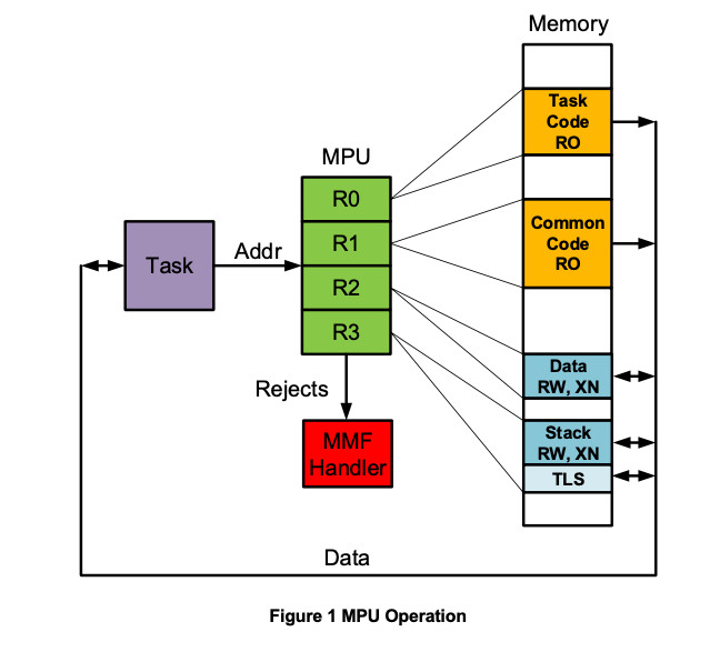
When the CPU attempts to access a memory address (to fetch an instruction or read/write data), the MPU checks if that access is allowed by the rules of the region(s) it falls into.
- If the access is allowed, it proceeds transparently.
- If the access is forbidden, the MPU blocks the access and triggers a high-priority exception, typically a
MemManage(Memory Management) fault.
This hardware-enforced separation is fundamental to modern embedded systems. It allows you to:
- Isolate RTOS Tasks: Prevent a bug in a low-priority task (e.g., UI) from corrupting the memory of a high-priority, safety-critical task (e.g., motor control).
- Protect the Kernel: Prevent application code from corrupting the RTOS kernel's internal data structures.
- Enforce Security Policies: Protect secret keys or critical boot code from being read or overwritten by untrusted application code.
- Detect Stack Overflows: Create a "guard" region just beyond a task's stack to immediately fault if the stack grows too large.
The diagram below shows a high-level view of the MPU acting as a gatekeeper. A task's memory request is checked against the MPU's configured regions. Any violation is rejected and triggers a fault handler.
To understand how the MPU achieves this, especially within an RTOS context, let's read an introductory white paper.
This white paper from Silicon Labs provides an excellent introduction to what an MPU is and why it's so valuable in RTOS-based applications. It explains the core concepts of memory isolation and fault handling.
Please read the first part of the document, from the beginning up to the section titled "Using the MPU of an ARM Cortex-M". Focus on understanding: The problem with traditional RTOS applications running entirely in privileged mode. How the MPU enables the concept of isolated "processes" or task groups. The mechanism of using a "RedZone" region to detect stack overflows.
2. Configuring an ARM Cortex-M MPU
Now, let's get practical. Configuring an MPU involves programming a set of dedicated registers. Your experience with AUTOSAR MCAL and driver development will be very relevant here, as this is a classic low-level configuration task. We'll focus on the popular Armv7-M architecture (found in Cortex-M3/M4/M7), as its principles are foundational.
To configure an MPU region, you must define its key attributes:
- Base Address: The starting address of the region.
- Size: The length of the region.
- Access Permissions: Who can access it (Privileged or Unprivileged code) and how (Read-Only or Read-Write).
- Executability: Whether the CPU is allowed to fetch and execute instructions from this region.
These attributes are programmed using three main MPU registers:
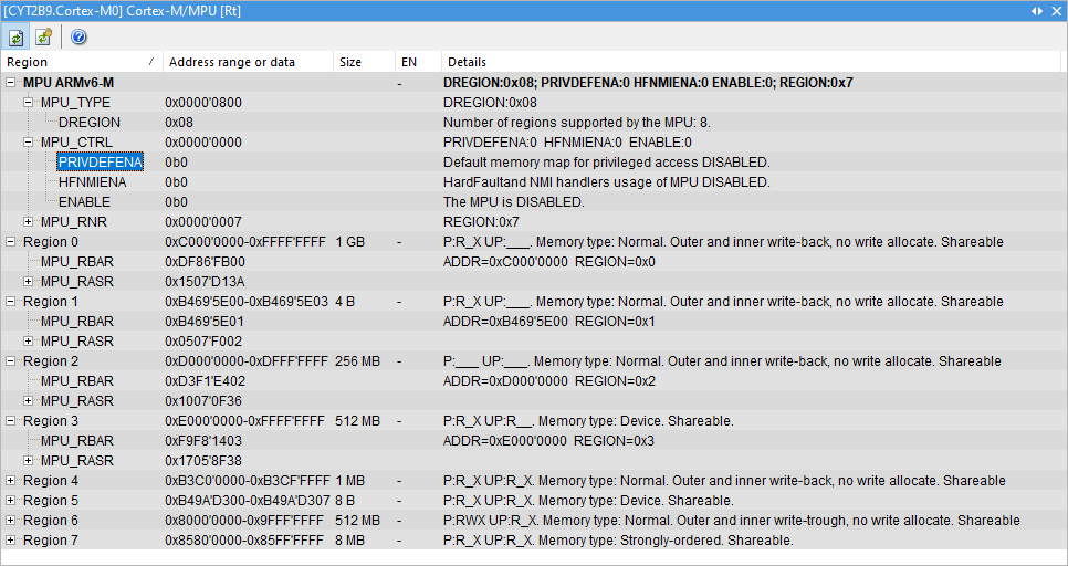
MPU_RNR(Region Number Register): Selects which region you are about to configure (e.g., region 0, 1, 2...).MPU_RBAR(Region Base Address Register): Sets the base address for the selected region.MPU_RASR(Region Attribute and Size Register): A packed register to configure the size, access permissions, and other attributes all at once.
Finally, the MPU_CTRL (Control Register) is used to enable the MPU itself.
The image below, from a debugger view similar to what you'd see in Lauterbach TRACE32, shows these registers and their bitfields.
Key Attributes in Detail
- Region Size and Alignment (Armv7-M): This is a critical point and a common interview question. In Armv7-M, region sizes must be a power of two (e.g., 32B, 64B, ..., 1KB, ..., 4GB), and the base address must be aligned to its own size. For example, a 4KB region must start on a 4KB boundary (e.g.,
0x20001000,0x20002000). This often leads to wasted memory if your actual data size isn't a neat power of two. - Access Permissions (
APbits): These three bits inMPU_RASRdefine the access rules. You can set permissions like "Privileged: RW, Unprivileged: RO" or "Privileged: RW, Unprivileged: No Access". - Execute Never (
XNbit): This powerful security feature inMPU_RASRprevents the processor from executing code from a memory region. You should always enable this for data regions like stacks and heaps to mitigate code injection attacks. This enforces the W^X (Write XOR Execute) security principle.
Let's dive into the specifics of these registers and the concept of organizing memory for an MPU.
We'll return to the "MPUs with an RTOS" white paper to see the concrete details of the Armv7-M MPU registers and how memory is typically organized.
Please read the sections titled "Using the MPU of an ARM Cortex-M" and "Creating the MPU Process Tables". Focus on: The description of the MPU registers in Figure 9. The explanation of the RASR bitfields (XN, AP, SIZE, etc.). The example of a process MPU table and how it defines regions for code, peripherals, RAM, and the stack RedZone. The important role the linker script plays in grouping data into contiguous sections that can be mapped to MPU regions.
3. A Practical MPU Configuration Example
Let's solidify this with a C code example using CMSIS-style functions, which you'll find in most vendor SDKs. Imagine we want to set up three basic regions for a simple application:
- Region 0: FLASH (Code): 256KB region for executable code. Should be Read-Only for Unprivileged code to prevent self-modification.
- Region 1: SRAM (Data): 32KB region for data and stack. Should be Read-Write but Execute Never.
- Region 2: Peripherals: A 4KB block for a specific peripheral (e.g., UART). Access should be restricted to Privileged code only.
Here is how you would configure this.
#include "ARMCM4.h" // Or the specific header for your Cortex-M core

void MPU_Setup(void) {
    // Ensure the MPU is disabled before configuration
    ARM_MPU_Disable();

    // --- Region 0: FLASH (256 KB) ---
    // Base Address: 0x00000000
    // Attributes: Read-Only for unprivileged, Executable
    ARM_MPU_SetRegion(
        0, // Region Number
        ARM_MPU_RBAR(0x00000000, ARM_MPU_SH_NON, 1, 0, 0), // Base Address, Non-shareable, RO, Privileged, Executable
        ARM_MPU_RASR(0, ARM_MPU_AP_RO, 0, 0, 0, 0, 0, ARM_MPU_REGION_SIZE_256KB) // XN=0, AP=RO, TEX/S/C/B=0, SRD=0, Size
    );

    // --- Region 1: SRAM (32 KB) ---
    // Base Address: 0x20000000
    // Attributes: Read-Write, Execute-NEVER
    ARM_MPU_SetRegion(
        1, // Region Number
        ARM_MPU_RBAR(0x20000000, ARM_MPU_SH_NON, 0, 1, 1), // Base Address, Non-shareable, RW, Unprivileged, XN
        ARM_MPU_RASR(1, ARM_MPU_AP_FULL, 0, 0, 1, 1, 0, ARM_MPU_REGION_SIZE_32KB) // XN=1, AP=Full Access, TEX=0, S=0, C=1, B=1, SRD=0, Size
    );

    // --- Region 2: UART Peripheral (4 KB) ---
    // Base Address: 0x4000C000 (Example address for a UART)
    // Attributes: Privileged RW only, Execute-NEVER
    ARM_MPU_SetRegion(
        2, // Region Number
        ARM_MPU_RBAR(0x4000C000, ARM_MPU_SH_NON, 0, 0, 1), // Base Address, Non-shareable, RW, Privileged, XN
        ARM_MPU_RASR(1, ARM_MPU_AP_PRIV, 1, 0, 0, 1, 0, ARM_MPU_REGION_SIZE_4KB) // XN=1, AP=Privileged Only, TEX=1, S=0, C=0, B=1, SRD=0, Size
    );

    // Enable the MPU and the default memory map for privileged code
    ARM_MPU_Enable(MPU_CTRL_PRIVDEFENA_Msk);

    // Memory barriers to ensure MPU settings are synchronized
    __DSB(); // Data Synchronization Barrier
    __ISB(); // Instruction Synchronization Barrier
}

int main(void) {
    MPU_Setup();

    // Application code runs here with MPU protection enabled
    // An unprivileged write to 0x00001000 would now cause a MemManage fault.
    // An instruction fetch from 0x20000000 would also cause a fault.

    while(1);
}
Test your understanding!
In the example above, an RTOS task is running in Unprivileged mode. It needs to send a debug message over UART. Will the code *(volatile uint32_t *)0x4000C000 = 'A'; succeed or fail? Why?
Show answer
It will fail and trigger a MemManage fault.
Region 2, which covers the UART peripheral at 0x4000C000, was configured with ARM_MPU_AP_PRIV. This setting allows Read-Write access for Privileged code but grants No Access to Unprivileged code. Since the task is running in Unprivileged mode, its attempt to write to this address is a violation of the MPU rules. The correct way to handle this in an RTOS is for the task to call a kernel API (an SVC), which temporarily switches to Privileged mode to perform the hardware access on the task's behalf.
4. Advancements in Armv8-M MPU
The job you're targeting mentions ARMv8 architecture. While the principles are the same, the MPU in Armv8-M (e.g., Cortex-M33/M55/M85) has significant improvements over Armv7-M. Knowing these differences is a sign of an up-to-date, senior engineer.
The two biggest improvements are:
- Flexible Region Sizing: The requirement for power-of-two sizes is gone. A region's start and end address only need to be 32-byte aligned. This dramatically reduces memory wastage.
- Non-Overlapping Regions: In Armv7-M, regions could overlap, with the highest-numbered region taking priority. In Armv8-M, regions are not allowed to overlap. This simplifies the mental model and makes configuration less error-prone.
Let's briefly consult a guide on the Armv8-M memory model to see a summary of these differences and the new configuration process.
Armv8-M Memory Model and Memory Protection User Guide
This user guide from ARM covers the newer Armv8-M MPU. We will use it to highlight the key differences from the Armv7-M MPU we just studied.
Please review the following two parts: "Differences between Armv7-M and Armv8-M MPU" (Table in Section 1.3): This table provides a perfect, concise summary of the key architectural changes. "Configuring an MPU region" (Figure 3-2 in Section 3.2.2): Look at the flowchart. Notice the new register names (MPU_RLAR for limit address) and the use of MAIR (Memory Attribute Indirection Register). This is different from the all-in-one RASR of Armv7-M.
5. Interview Corner
Q1: Why is an MPU a critical component for systems requiring functional safety under ISO 26262?
A: ISO 26262 requires "freedom from interference" between software components, especially those with different ASIL ratings. An MPU is the primary hardware mechanism to enforce this. It creates spatial isolation, ensuring that a fault in a low-ASIL component (like a QM-rated HMI task) cannot corrupt the memory space of a high-ASIL component (like an ASIL-D-rated braking algorithm). This prevents fault propagation and is a key technical safety concept.
Q2: You need to protect a 5KB block of calibration data in an Armv7-M system. How would you configure the MPU region? What is the main drawback?
A: On an Armv7-M core, MPU region sizes must be a power of two. To cover a 5KB block, I would have to configure an 8KB region, as that's the next power-of-two size up from 4KB. The base address would need to be 8KB-aligned. The main drawback is wasted memory: 3KB of the 8KB region would be "protected" but unused, or it might unintentionally cover other unrelated data, which could complicate the memory map.
Q3: How does an RTOS use the MPU to isolate tasks? What happens during a context switch?
A: The RTOS assigns each task (or group of tasks) a specific memory map defining its code, data, and stack regions. During a context switch, just before switching to a new task, the scheduler performs an extra step: it reprograms the MPU with the memory configuration specific to that incoming task. This ensures that when the task starts executing, it runs within its own "sandbox," with the MPU hardware enforcing its memory boundaries.
Q4 (Advanced): You are debugging an MPU fault. The MemManage Fault Status Register indicates a data access violation (DACCVIOL is set), and the MMFAR register holds a valid address. What are your first steps to identify the root cause?
A: Given my experience with Lauterbach, my first step would be to set a breakpoint in the MemManage_Handler. When the fault occurs, the debugger will halt.
- Examine the Fault Registers: I'd inspect the
MMFARto see the exact memory address that caused the fault. I'd also check the rest of the fault status register to confirm it was a data write/read violation. - Analyze the Faulting Instruction: The stacked program counter (
PC) on the stack points to the instruction that would have executed after the faulting one. By disassembling the code around that address, I can find the exactLDRorSTRinstruction that caused the fault. - Check the MPU Configuration: I would then use the debugger to inspect the current MPU region settings (
MPU_RBAR/MPU_RASRregisters) to understand why the access to the address inMMFARwas forbidden. I'd check if the address falls outside all defined regions or if the access type (e.g., an unprivileged write to a privileged-only region) violated the permissions. - Trace Backwards: Using the call stack, I can trace back to see which function and task was executing, giving me the context to understand why that faulty memory access was attempted.
Conclusion
Today, we've taken a significant step from simply detecting errors to proactively preventing them. The MPU is a powerful hardware tool that, when used correctly, provides the foundation for building safe, secure, and reliable embedded systems.
Key Takeaways:
- An MPU enforces memory access rules in hardware, triggering a fault on any violation.
- It is essential for achieving spatial isolation and freedom from interference, core principles of functional safety.
- Configuration involves setting a region's base address, size, access permissions (
AP), and executability (XN). - In an RTOS, the MPU is reconfigured on every context switch to provide a unique memory "sandbox" for each task.
- Modern Armv8-M MPUs offer more flexibility (e.g., arbitrary region sizes) compared to the stricter power-of-two constraints of Armv7-M.
Next Lesson Preview
Configuring the MPU is a perfect example of a "software safety mechanism." In our next lesson, we will broaden our scope and dive directly into Functional Safety for Driver Development (ISO 26262). We will discuss how to apply key principles from ISO 26262 Part 6 (Software) to the drivers you develop, covering techniques like defensive programming, parameter validation, and implementing other software safety mechanisms. This MPU lesson has laid the perfect groundwork for that discussion.