Hello! Welcome to the next lesson in your preparation for senior embedded driver development roles.
In our last lesson, we focused on "preemptive programming," building robust driver APIs with parameter validation, range checks, and plausibility checks. We established how to create a contract at the software interface to detect and report bugs immediately.
Today, we move from protecting software interfaces to ensuring the fundamental integrity of the hardware and the program's execution flow. These are core requirements under ISO 26262 for detecting hardware faults and recovering from software hangs. Your learning outcome for this lesson is to implement a startup RAM test (e.g., March C-) and a periodic watchdog refresh mechanism. Mastering these two safety mechanisms is non-negotiable for the roles you are targeting.
1. Ensuring Memory Integrity: The Startup RAM Test
Before your application can trust any variable or data structure, you must first trust the physical RAM it resides in. Silicon is not perfect, and memory cells can fail. ISO 26262 mandates that safety-critical systems test their RAM to detect such hardware faults. The March test algorithms are the industry standard for this.
Understanding March Test Algorithms
March tests are a family of algorithms that write and read patterns to every cell in a memory array to expose various types of faults. These faults include:
- Stuck-at Faults: A memory bit is permanently stuck at 0 or 1.
- Transition Faults: A cell fails to transition from 0 to 1, or vice-versa.
- Coupling Faults: A transition in one memory cell (the aggressor) incorrectly flips the value of another cell (the victim).
- Address Decoder Faults: Writing to one address incorrectly accesses another, or multiple, or no addresses.
To understand how these algorithms are constructed and how they evolved to detect more fault types, please watch the following video. It provides an excellent, concise overview.
This video, "MemTest March," breaks down the notation of March tests and walks through the evolution from simple algorithms to the more comprehensive March C-.
Watch the entire video (up to 24:45). Focus on: The Notation (00:07): Understand what w0, r0, ↑, ↓ signify. March A (03:22): A simple, early algorithm. March X (10:18): How a small change helps detect coupling faults. March C (16:13): A more powerful algorithm that detects a wider range of coupling faults. March C- (22:33): The refined, non-redundant version of March C, which is our main focus.
The March C- Algorithm
As you saw, March C- is an optimized version of March C. It's often chosen in practice because it provides excellent fault coverage with a complexity of 10n (where n is the number of memory locations), making it one of the most efficient tests for its capabilities.
The notation for March C- is: { (w0); ↑(r0, w1); ↑(r1, w0); ↓(r0, w1); ↓(r1, w0); (r0) }
Let's break that down into steps:
(w0): Initialize the entire memory block by writing 0s. The address order doesn't matter.↑(r0, w1): March up through memory. For each address: read it (expect 0), then write a 1.↑(r1, w0): March up again. For each address: read it (expect 1), then write a 0.↓(r0, w1): March down through memory. For each address: read it (expect 0), then write a 1.↓(r1, w0): March down again. For each address: read it (expect 1), then write a 0.(r0): Read the entire block, expecting 0s. The address order doesn't matter.
This sequence of operations is specifically designed to provoke and then detect the fault models we discussed earlier.
Practical Implementation
A startup RAM test is typically destructive, meaning it overwrites the contents of the memory. This is acceptable at boot because the RAM (specifically the .bss and .data sections) has not yet been initialized by the C runtime startup code. Therefore, the RAM test must run before this initialization happens.
The following application note from Microchip provides excellent pseudocode for implementing a March C test. We will focus on the C- variant.
This Microchip Application Note, "AN1778," describes software for meeting safety standards. It contains a clear description and pseudocode for the March C/C- test.
Please read the section "MARCH C/C- TEST" and review "EXAMPLE 1: PSEUDOCODE FOR MARCH C TEST". Then read the description for the CLASSB_RAMMarchCTest API. Note the following practical details: The distinction between destructive and non-destructive modes. The statement that "this test can be executed at the system start-up before initializing the memory." The important fact that "interrupts are disabled during the test."
Here is a C implementation of March C- based on that pseudocode, adapted for clarity. This would be called from your assembly startup file or as the very first function in main().
#include <stdint.h>

// Define a type for the test result
typedef enum {
    RAM_TEST_PASSED,
    RAM_TEST_FAILED
} ram_test_result_t;

/**
 * @brief Performs a destructive March C- test on a memory region.
 *
 * @param start_addr Pointer to the start of the memory region to test.
 * @param end_addr Pointer to the end of the memory region to test.
 * @return ram_test_result_t RAM_TEST_PASSED or RAM_TEST_FAILED.
 */
ram_test_result_t ram_march_c_minus_test(volatile uint32_t* start_addr, volatile uint32_t* end_addr) {
    volatile uint32_t* p;

    // The test must be run with interrupts disabled to prevent corruption.
    // __disable_irq(); // CMSIS intrinsic

    // 1. { (w0) } - Write 0 to all locations (ascending)
    for (p = start_addr; p <= end_addr; p++) {
        *p = 0x00000000;
    }

    // 2. { ↑(r0, w1) } - Read 0, Write 1 (ascending)
    for (p = start_addr; p <= end_addr; p++) {
        if (*p != 0x00000000) return RAM_TEST_FAILED;
        *p = 0xFFFFFFFF;
    }

    // 3. { ↑(r1, w0) } - Read 1, Write 0 (ascending)
    for (p = start_addr; p <= end_addr; p++) {
        if (*p != 0xFFFFFFFF) return RAM_TEST_FAILED;
        *p = 0x00000000;
    }

    // 4. { ↓(r0, w1) } - Read 0, Write 1 (descending)
    for (p = end_addr; p >= start_addr; p--) {
        if (*p != 0x00000000) return RAM_TEST_FAILED;
        *p = 0xFFFFFFFF;
    }

    // 5. { ↓(r1, w0) } - Read 1, Write 0 (descending)
    for (p = end_addr; p >= start_addr; p--) {
        if (*p != 0xFFFFFFFF) return RAM_TEST_FAILED;
        *p = 0x00000000;
    }

    // 6. { (r0) } - Read 0 (ascending)
    for (p = start_addr; p <= end_addr; p++) {
        if (*p != 0x00000000) return RAM_TEST_FAILED;
    }

    // __enable_irq(); // Re-enable interrupts if they were disabled here
    return RAM_TEST_PASSED;
}

// Example usage early in main():
// extern uint32_t __bss_start__[];
// extern uint32_t __bss_end__[];
// if (ram_march_c_minus_test(__bss_start__, __bss_end__ - 1) == RAM_TEST_FAILED) {
//     // Handle failure: e.g., enter a safe state, blink an error LED.
//     while(1);
// }
Note: The pointers are declared volatile to ensure the compiler does not optimize away the memory accesses, which would render the test useless.
2. Ensuring Temporal Safety: The Watchdog Mechanism
A RAM test verifies hardware integrity at startup. A watchdog timer (WDT) verifies software integrity at runtime. Its purpose is to detect if the program has frozen, deadlocked, or gone off into an unintended state, and to trigger a reset to recover.
Watchdog Fundamentals
A hardware watchdog is a simple counter that is independent of the main CPU clock. If the software does not periodically reset ("feed" or "kick") this counter before it times out, the watchdog hardware will force a system reset.
A Guide to Watchdog Timers for Embedded Systems - Interrupt
This blog post, "A Guide to Watchdog Timers for Embedded Systems," is a comprehensive and practical guide to using watchdogs effectively. It will form the basis for this part of the lesson.
First, please read the introductory sections: "The Hardware Watchdog," "Why should I use a Watchdog?," and "Configuring a Hardware Watchdog." This covers the fundamental concepts and crucial configuration questions to ask when reading a microcontroller datasheet.
A common enhancement is the Window Watchdog (WWDG). It defines a time window during which a feed is allowed. Feeding too early is also considered a fault, which prevents a bug where a malfunctioning, high-frequency loop could keep feeding the watchdog and masking a system hang.
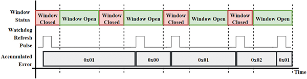
Building a Robust Refresh Strategy
A naive watchdog implementation, where you simply call watchdog_feed() in your main() loop, is a common but dangerous mistake. It can detect a complete freeze but fails to detect more subtle issues like task deadlocks in an RTOS.
The Interrupt blog post walks through this exact scenario, demonstrating how a simple watchdog fails and then presenting a much more robust solution.
A Guide to Watchdog Timers for Embedded Systems - Interrupt
Now, let's see why a simple watchdog feed is not enough and how to build a proper one.
Please read the sections "A Basic Implementation" through "Retry 'Hang waiting for a mutex'". Pay close attention to: How the simple low-priority task approach fails to detect a mutex deadlock. The concept of the "Task Watchdog": a software layer where multiple tasks must check in before the hardware watchdog is fed. The C code example showing how to implement this task monitoring logic.
The core idea is logical monitoring. The hardware watchdog is only fed if all critical software components prove they are alive and making progress. Each critical task is responsible for periodically "checking in" with a central watchdog manager.
Here's an implementation of that software watchdog manager concept:
#define MAX_WATCHED_TASKS 8

// A bitmask of all tasks that have registered with the watchdog
static uint32_t g_registered_tasks_mask = 0;
// A bitmask of tasks that have checked in during the current window
static uint32_t g_checked_in_tasks_mask = 0;

void watchdog_manager_register(uint8_t task_id) {
    if (task_id < MAX_WATCHED_TASKS) {
        // ATOMIC_OP_START();
        g_registered_tasks_mask |= (1 << task_id);
        // ATOMIC_OP_END();
    }
}

void watchdog_manager_check_in(uint8_t task_id) {
    if (task_id < MAX_WATCHED_TASKS) {
        // ATOMIC_OP_START();
        g_checked_in_tasks_mask |= (1 << task_id);
        // ATOMIC_OP_END();
    }
}

// This function should be called periodically by a timer or low-priority task.
void watchdog_manager_evaluate() {
    // ATOMIC_OP_START();
    // Check if all registered tasks have checked in
    if (g_checked_in_tasks_mask == g_registered_tasks_mask) {
        // All alive, so feed the hardware watchdog
        hardware_watchdog_feed();
        // And reset the check-in mask for the next window
        g_checked_in_tasks_mask = 0;
    } else {
        // At least one task has not checked in.
        // Do NOT feed the watchdog. A reset will occur.
        // For debugging, we could log which tasks failed to check in:
        // uint32_t missed_tasks = g_registered_tasks_mask & ~g_checked_in_tasks_mask;
        // log_error("Watchdog timeout imminent! Missed tasks: %x", missed_tasks);
    }
    // ATOMIC_OP_END();
}
An even more robust method is a challenge-response watchdog, where the watchdog provides a value (the challenge) and the software must compute and return the correct answer. This ensures not only that tasks are running, but that they are executing correctly.

Test your understanding!
You have an RTOS-based system with three critical tasks:
- A CAN communication task (high priority, periodic).
- A sensor data processing task (medium priority, event-driven).
- A logging task (low priority, periodic).
How would you design a watchdog strategy using the task monitoring pattern? Where would each task "check in"?
Show answer
- Register all three tasks with the
watchdog_managerat initialization. - CAN Task: Checks in at the end of its main processing loop, after successfully transmitting and receiving messages for that cycle.
- Sensor Task: Checks in after it successfully processes a sensor data event. If it can be idle for long periods, it might need to
unregisterwhile waiting for an event andregisteragain when it starts processing, to avoid causing timeouts. - Logging Task: Checks in at the end of its loop after successfully writing to the log.
- A separate, very low-priority task or a hardware timer interrupt would periodically call
watchdog_manager_evaluate()to check the status and feed the hardware WDT if all conditions are met.
Debugging Watchdog Resets
A system that keeps resetting is hard to debug. The first step is to confirm the cause. Microcontrollers provide a reset reason register that indicates what triggered the last reset (e.g., power-on, external pin, or watchdog). You should read and log this register at the very beginning of boot.
The ultimate debugging technique is to catch the system before the hardware watchdog fires.
A Guide to Watchdog Timers for Embedded Systems - Interrupt
This final reading shows you how to transform a watchdog reset from a mysterious event into a debuggable fault.
Please read the sections "Root Causing Watchdogs" and "Debugging our example hangs." This introduces the powerful concept of a "Software Watchdog": using a separate timer with a shorter timeout to trigger a fault handler, allowing you to capture a coredump and analyze the system state just before the actual hardware reset would have occurred.
This "software watchdog" is a critical technique for your toolkit. It allows you to get a full stack trace and memory dump, turning a difficult "the system just hangs" problem into a solvable bug.
Conclusion
In this lesson, you've learned to implement two pillars of functional safety: startup memory diagnostics and runtime execution monitoring.
Key Takeaways:
- March C- Test: An efficient, industry-standard algorithm to verify RAM integrity at startup. It must be run early in the boot sequence, before C-runtime initialization, and with interrupts disabled.
- Watchdog Timers: A fail-safe mechanism to recover from software hangs. A window watchdog provides more safety than a simple one.
- Robust Watchdog Strategy: A simple watchdog feed is insufficient for complex systems. A robust strategy involves a task monitoring software layer, where the hardware watchdog is only fed if all critical tasks have "checked in."
- Debugging Watchdogs: To find the root cause of a hang, first check the reset reason register. For deep analysis, implement a software watchdog (using a timer) to trigger a fault handler before the hardware reset, allowing you to capture the system state.
Next Lesson Preview
We have now covered safety at the API boundary, memory integrity, and temporal monitoring. Next, we will focus on spatial separation. You will learn how to configure a Memory Protection Unit (MPU) to create isolated memory regions for protecting critical assets from unauthorized access. This is a fundamental technique for preventing faults in one software component from corrupting another, a key requirement of ISO 26262.