Hello! Welcome to your next lesson on functional safety for driver development.
In our last lesson, we focused on hardware integrity and temporal safety. You learned how to implement a startup RAM test (March C-) to verify memory hardware and how to use a robust watchdog strategy to monitor runtime execution flow and recover from hangs. These mechanisms ensure the system starts in a known-good state and remains responsive over time.
Today, we shift our focus from "when" things execute to "where" they execute. The learning outcome is to configure a Memory Protection Unit (MPU) to enforce spatial separation between software elements to prevent interference. This is a cornerstone of ISO 26262, especially in complex systems like the ones you've worked on, where software components with different safety levels (e.g., QM vs. ASIL) coexist on the same microcontroller.
1. The Problem: The Danger of Unrestricted Memory Access
In a simple embedded system without an MPU, all software—the RTOS kernel, drivers, and application tasks—typically runs in a single, privileged mode with access to the entire memory map. A bug in any single component can have catastrophic consequences.
To understand the risks inherent in this model, please watch this first video segment.
Intro To Rtos by Jean J. Labrosse
Jean J. Labrosse, the creator of the μC/OS RTOS, explains the vulnerabilities of a system running without an MPU in this segment from his talk, "Intro To Rtos."
Watch from 35:52 to 38:08. Focus on the key problems he identifies: Any task or ISR has full access to the entire memory space. The potential for one task to tamper with another. The inability to detect stack overflows in hardware. The risk of code injection attacks (executing code from RAM).
As the video highlights, without hardware-enforced boundaries, a stray pointer in a low-priority, non-critical task could corrupt a critical variable used by a high-priority, safety-critical task. This is known as memory interference.
In the context of ISO 26262, where you might have Quality Managed (QM) software running alongside ASIL B or ASIL D components, this is unacceptable. A fault in the QM component must not cause a failure in the ASIL component. This principle is called Freedom From Interference (FFI).
This next short video segment frames the problem specifically within the context of automotive functional safety.
Automotive Functional Safety ISO26262 Systems Part 4 Webinar
This clip from the webinar "Automotive Functional Safety ISO26262 Systems Part 4" discusses memory interference between different ASIL levels and introduces the MPU as a solution.
Watch from 05:11 to 07:00. Note how the presenter lists the same fault models we've discussed (corruption, stack overflow, incorrect access) and identifies the MPU as the primary mechanism to prevent them.
2. The MPU: A Hardware Firewall for Your Memory
A Memory Protection Unit (MPU) is a hardware peripheral, usually integrated into the CPU core (like ARM Cortex-M/R), that enforces memory access rules. It acts like a firewall, preventing unauthorized access between different software modules.
Core MPU Concepts
The MPU works by dividing memory into a set of regions. For each region, you can define specific access attributes. The key concepts are:
- Region: A configurable block of memory defined by a start address and a size. Modern MPUs typically offer 8 or 16 regions.
- Access Permissions: For each region, you can specify permissions for privileged and unprivileged code, such as:
- Read/Write
- Read-Only
- No Access
- Execute Never (XN): A crucial attribute that prevents the CPU from fetching and executing instructions from a memory region, such as RAM. This is a primary defense against code injection attacks.
The system is then divided into two main CPU privilege levels:
- Privileged Mode: The RTOS kernel, MPU configuration code, and other trusted parts of the system run in this mode. It has full access rights and can configure the MPU.
- Unprivileged (or User) Mode: Application tasks run in this mode. Their memory access is restricted by the MPU rules. They cannot change MPU settings or execute privileged instructions (like disabling interrupts).
This model ensures that an application task cannot maliciously or accidentally reconfigure the MPU to give itself more access.

The following video segments explain how these concepts come together to create "fences" around tasks.
Intro To Rtos by Jean J. Labrosse
Let's return to Jean Labrosse's talk, where he explains how an MPU is used to create process separation and the benefits this provides.
Watch from 01:04:17 to 01:07:12. Focus on: The MPU creating 'fences' around tasks and their associated memory. User tasks running in non-privileged mode, preventing them from accessing hardware like the interrupt controller. The ability of the MPU to detect stack overflows in hardware, a significant reliability improvement.
3. Implementing MPU-based Spatial Separation
Configuring the MPU involves defining a partitioning strategy and then translating that strategy into register-level settings. Given your AUTOSAR background, you'll find the concepts map very cleanly to the AUTOSAR OS model.
Step 1: Design a Memory Partitioning Strategy
Before writing any code, you must decide how to partition the system. This is a system architecture decision.
Overview of Functional Safety Measures in AUTOSAR
This document, "Overview of Functional Safety Measures in AUTOSAR," is essential reading. It directly connects the ISO 26262 requirement for memory partitioning to the AUTOSAR OS architecture.
Please read the following sections: Section 2.1 Memory Partitioning: This introduces the concept and its relation to FFI. Section 2.1.2 Description: Read up to and including 2.1.2.2 OS Applications. This explains how AUTOSAR groups OS objects (Tasks, ISRs) into OS-Applications, and how these can be either Trusted or Non-Trusted. Section 2.1.2.6 Implementation of Memory Partitioning: This is the most critical section. It shows how the MPU is the underlying hardware for implementing AUTOSAR memory partitioning. Pay close attention to Figure 8, which shows a typical automotive configuration with BSW in a trusted partition and SW-Cs in non-trusted partitions.
As the document explains, an AUTOSAR OS-Application is the unit of memory protection.
- A Trusted OS-Application runs in privileged mode. It contains the OS, MCAL drivers, and other trusted BSW modules. Its access is unrestricted.
- A Non-Trusted OS-Application runs in unprivileged mode. It contains application SW-Cs. Its access is restricted by the MPU.
- Code within one Non-Trusted OS-Application is prevented from accessing the memory of another Non-Trusted OS-Application.
This provides spatial separation between different functional domains (e.g., an ASIL-D braking application is protected from a QM infotainment application).
Finer-grained partitioning is also possible, such as at the task level. For a deeper dive into different design choices, the paper "Memory Interference Mitigation" provides an excellent overview of strategies like Partial ASIL, Full ASIL, and Task-level partitioning. You can explore section 4.2.1 of this paper (LINK) later for more advanced concepts.
Step 2: Configure the MPU Registers
Once you have a partitioning map, you implement it by writing to the MPU's configuration registers. This is typically done by the OS or a low-level startup module running in privileged mode.
The process involves:
- Disabling the MPU.
- Configuring each region:
- Set the region's base address in a Region Base Address Register (RBAR).
- Set the region's size, access permissions, and XN bit in a Region Attribute and Size Register (RASR).
- Enabling the MPU.
The following code snippet, from the "Memory Interference Mitigation" paper, shows a practical example of how one might define a data protection range on a TriCore architecture. The principles are very similar for ARM.
// From "Memory Interference Mitigation..." (Listing 5.3) for TriCore,
// conceptual equivalent for ARM would use CMSIS functions.
void define_dpr(unsigned long lowerBound, unsigned long upperBound, unsigned char dpr) {
    // Switch to the selected data protection range and set lower/upper bounds
    switch (dpr) {
        case DPR_0:
            // __mtcr is a special instruction to "move to core register"
            __mtcr(CPU_DPR0_L, lowerBound);
            __mtcr(CPU_DPR0_U, upperBound);
            break;
        // ... cases for other regions
    }
    // Instruction Synchronization Barrier to ensure the change takes effect
    __isync();
}
For ARM Cortex-M, CMSIS provides helper functions like HAL_MPU_ConfigRegion() or direct register access structs, simplifying this process.
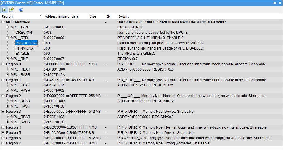
When debugging, you can use your JTAG debugger to inspect the MPU configuration directly.
Test your understanding! (Interview Question)
You are tasked with protecting the registers of a CAN controller from being accidentally written to by an untrusted application task. The CAN registers reside at memory address 0x40006400 to 0x400067FF. The MCAL CAN driver needs full access. How would you configure an MPU region for this?
Show answer
- Define a Region: Configure one of the MPU's regions to cover the address range
0x40006400to0x400067FF. The size would be 1 KB. - Set Access Permissions:
- Privileged Access: Set to Read/Write (
RW). This allows the trusted CAN driver (running as part of the privileged BSW) to access the registers. - Unprivileged Access: Set to No Access (
NA). This blocks any read or write attempts from the untrusted application task.
- Privileged Access: Set to Read/Write (
- Set Execute Never (XN): The XN bit for this region should be set to
1(enabled), as there is no reason to ever execute code from a peripheral memory region.
This configuration ensures that only trusted, privileged code can interact with the CAN controller hardware.
Step 3: Handling MPU Faults
When a task in unprivileged mode attempts to violate an MPU rule (e.g., writing to a read-only area), the MPU blocks the access and triggers a hardware exception. On ARM Cortex-M, this is typically a MemManage Fault.
The system must have a handler for this fault. In an AUTOSAR system, this is managed by the OS.
Overview of Functional Safety Measures in AUTOSAR
Let's return to the AUTOSAR Functional Safety document to see how it specifies the detection and reaction to MPU violations.
Please read section 2.1.3 Detection and Reaction. It explains that the hardware raises an exception, which is handled by the OS. Note the mention of configurable reactions, such as partition shutdown or restart, implemented via a Protection Hook. This is a key concept in AUTOSAR error handling.
The ProtectionHook is a user-configurable function called by the OS when a protection violation occurs. This allows the system architect to define the appropriate recovery action. For a severe fault, the action might be to shut down the offending OS-Application. For less critical errors, it might just log the error and terminate the faulty task.
4. Advanced Considerations and Limitations
While powerful, the MPU is not a silver bullet. A senior developer should be aware of its limitations and advanced use cases.
- Performance Overhead: While the MPU check itself is done in hardware with no overhead, switching MPU contexts during task switches does add a small performance penalty. This is a trade-off for the greatly increased safety and reliability.
- DMA and other Bus Masters: A standard CPU-integrated MPU only protects against accesses originating from that CPU core. It does not protect against accesses from other bus masters like a DMA controller. If you configure a DMA transfer to write to a protected memory area, it will succeed, bypassing the MPU. This is a critical security and safety vulnerability that must be addressed at the system design level, for instance by using a system-level MPU (sometimes called SPU or Firewall) if available, or by carefully validating all DMA configurations.
- Configuration Complexity: Correctly partitioning a complex system and managing the linker configuration to place code and data into the right sections is a non-trivial task. It requires careful planning and rigorous testing. The static analysis described in the "Memory Interference Mitigation" paper (section 5.4 of LINK), which checks for region alignment and overlap, is a best practice.
Conclusion
You have now learned how to enforce spatial separation, a critical safety requirement. This complements the temporal safety (watchdogs) and hardware integrity checks (RAM tests) we covered previously.
Key Takeaways:
- Spatial Separation: The MPU is the primary hardware mechanism for enforcing Freedom From Interference (FFI) between software components, a core principle of ISO 26262.
- Privilege Levels: The MPU enables a system with privileged (trusted kernel/drivers) and unprivileged (untrusted application tasks) modes. Unprivileged tasks have their memory access restricted.
- Regions and Attributes: An MPU is configured with regions, each having specific access permissions (Read, Write, No Access) and an Execute Never (XN) attribute to prevent code execution from data memory.
- AUTOSAR Mapping: In AUTOSAR, the
OS-Applicationis the unit of memory protection.Trusted OS-Applicationsrun in privileged mode, whileNon-Trusted OS-Applicationsrun in unprivileged mode under MPU supervision. - Fault Handling: An MPU violation triggers a hardware fault (e.g., MemManage Fault), which is caught by the OS. The system's reaction is often configurable via a
ProtectionHook.
Next Lesson Preview
We have covered several software and hardware mechanisms for detecting and mitigating faults. In the next lesson, we will continue this theme by looking at another important diagnostic for hardware. You will learn how to implement a register read-back test to diagnose hardware peripheral faults. This technique helps ensure that your peripheral hardware is configured correctly and has not been affected by a transient fault.