Introduction
Welcome to your first lesson in building embedded systems. Our journey begins at the very heart of the microcontroller: the processor core. The STM32 boards you have are built around an ARM Cortex-M processor. Understanding its architecture is the first, crucial step toward mastering embedded systems, moving from basic builds to the professional-grade hardware you aim to create. It provides the "rules of the game" that all our software will have to follow.
This lesson addresses the first learning outcome of our course: to describe the ARM Cortex-M processor architecture, including its registers, operating modes, and execution model. Think of this as learning the fundamental API of the CPU itself. For a software engineer, this is analogous to understanding the architecture of a desktop CPU (like x86-64) and its relationship with the operating system, but here we are much closer to the hardware. We'll cover the processor's internal data storage (registers), the different states it can operate in (modes), and how it transitions between them to run your code and respond to real-world events.
What is a Processor Architecture?
Before diving into the specifics of the Cortex-M, let's clarify what we mean by "processor architecture." In essence, it is the programmer's view of the processor—the set of rules and resources available for writing software. This is often formally called the Instruction Set Architecture (ISA).
To get a concise overview of what an ISA entails, please watch the beginning of the following video. It introduces the key components that define a processor's architecture from a programmer's perspective.
01: ARM Cortex-M Instruction Set Architecture
This video from the channel JoeTheProfessor provides a clear, conceptual introduction to Instruction Set Architectures.
Please watch from the beginning until the presenter starts discussing registers at this point. Focus on how it defines the ISA in terms of registers, memory, and I/O devices.
As the video explains, the ISA is a contract between the software and the hardware. The Cortex-M family you'll be working with has several members (Cortex-M0, M3, M4, M7, etc.), each implementing a specific version of the ARM architecture (e.g., ARMv6-M, ARMv7-M). Your STM32 board likely has a Cortex-M4 or similar core. While these cores have performance and feature differences, they share a common architectural foundation, which is our focus today.
The Programmer's Model: Registers
The most immediate resources a processor provides are its registers. These are small, extremely fast storage locations inside the CPU core used for temporary data, calculations, and controlling program flow. The ARM Cortex-M architecture defines a set of 16 core 32-bit registers.
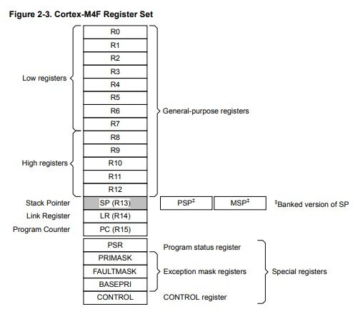
These registers can be grouped into two main categories:
-
General-Purpose Registers (R0 - R12): These are the workhorse registers for data manipulation. You can use them to hold variables, pointers, and intermediate results of calculations. Although they are "general purpose," programming conventions (specifically, the ARM Procedure Call Standard, which we'll cover later) assign specific roles to some of them during function calls.
-
Special-Purpose Registers (R13, R14, R15): These three registers have roles defined by the processor hardware itself.
- R13 (Stack Pointer, SP): The stack is a critical data structure in RAM used for function calls, local variables, and saving context during interrupts. The SP always points to the "top" of the stack. A key feature of Cortex-M is that the stack pointer is banked, meaning there are actually two of them: the Main Stack Pointer (MSP) and the Process Stack Pointer (PSP). The processor can only use one at a time, and the choice is determined by the processor's operating mode, which we will discuss shortly. This is a crucial feature for operating systems.
- R14 (Link Register, LR): When your code calls a function (a
BLor Branch with Link instruction in assembly), the processor automatically saves the return address—the address of the instruction immediately after the call—into the LR. When the function finishes, it can use the value in the LR to return to the caller. - R15 (Program Counter, PC): This is one of the most important registers. The PC always holds the memory address of the next instruction to be executed. As the processor fetches an instruction, it automatically increments the PC to point to the next one. Branching and function calls are achieved simply by writing a new address into the PC.
Beyond these, there are several Special Registers that control the processor's state. The most important ones for now are:
- Program Status Registers (PSR): Holds status flags from recent operations (e.g., Negative, Zero, Carry, Overflow flags), the current instruction set state, and the active exception number.
- CONTROL Register: A key register used to switch between processor privilege levels and to select which stack pointer (MSP or PSP) is currently active.
For a more detailed breakdown of these registers and their roles, the official ARM white paper is an excellent resource.
This document from ARM provides an authoritative overview of the Cortex-M architecture. We will focus on the section describing the programmer's model.
Please read section 3.1, "Programmer’s model." Pay close attention to the description of the general registers and the introduction to the special registers. The diagram in this section is the one we looked at above.
Operating Modes and Privilege Levels
One of the most powerful concepts in the Cortex-M architecture is its set of operating modes and privilege levels. This system is fundamental to writing robust and secure software, and it's what enables a real-time operating system (RTOS) to safely manage multiple tasks.
The processor operates in one of two modes:
- Thread Mode: The default mode for executing your main application code.
- Handler Mode: A special mode the processor enters automatically to handle an exception or interrupt (e.g., a timer expiring, data arriving on a serial port, or a software fault).
Independent of the mode, the processor is also always at one of two privilege levels:
- Privileged Level: Has full access to all processor features, instructions, and memory.
- Unprivileged Level: Has restricted access. Certain instructions are disabled, and memory access can be limited by a Memory Protection Unit (MPU), if present.
Combining these gives us the following execution states:
- Handler Mode is always Privileged. This is critical. It ensures that interrupt handlers have the necessary access to control the system and recover from faults.
- Thread Mode can be either Privileged or Unprivileged. When the processor first boots, it starts in Privileged Thread Mode. Software can then choose to switch to Unprivileged Thread Mode to run application code with fewer permissions.
This separation is analogous to the "kernel space" versus "user space" distinction in desktop operating systems. The OS kernel runs in a privileged state, while user applications run in an unprivileged state, preventing a faulty application from crashing the entire system.
The following flowchart illustrates the possible transitions.

As the diagram shows, the only way for unprivileged code to execute privileged operations is to trigger an exception. This forces a transition into the always-privileged Handler Mode. An application can do this deliberately using an SVC (Supervisor Call) instruction, which is the standard mechanism for an application task to request services from an underlying OS kernel.
This dual-stack pointer system (MSP vs. PSP) we mentioned earlier maps directly onto this model. Privileged code (Handler mode and Privileged Thread mode) typically uses the Main Stack Pointer (MSP). Unprivileged application tasks are configured to use the Process Stack Pointer (PSP). This provides stack isolation, so a stack overflow in one unprivileged task cannot corrupt the stack of the kernel or other tasks.
The following video provides an excellent walkthrough of these modes and their significance.
Deep dive in ARM Cortex-M Architecture with Microchip
This segment from a deep dive by Elektor TV and Microchip clearly explains the processor's operating modes and the concept of privilege levels.
Please watch the section covering processor modes, from this timestamp. Pay close attention to the diagrams that build up from a simple Thread/Handler model to one that includes the Privileged/Unprivileged dimension.
The Cortex-M Execution Model
Now, let's synthesize these concepts into a coherent execution model.
-
Instruction Set: All Cortex-M processors operate exclusively in the Thumb state, executing the Thumb-2 instruction set. This is a mixed 16-bit and 32-bit instruction set optimized for high code density and performance, which is ideal for memory-constrained embedded systems. This differs from older "classic" ARM processors which had two separate operating states (ARM and Thumb).
-
Execution Flow: Upon reset, the processor begins execution in Privileged Thread Mode, using the Main Stack Pointer (MSP). It fetches its initial stack pointer value and the starting address of the reset handler code from a special region in memory called the vector table.
-
Interrupt Handling: The defining feature of the Cortex-M execution model is its efficient, hardware-driven exception handling. When an interrupt occurs:
- If the interrupt has a higher priority than the current execution level, the processor automatically stops what it's doing.
- It pushes a block of 8 registers (including the PC, LR, and PSR) onto the current stack (either MSP or PSP). This is called stacking.
- It switches into Handler Mode (which is always privileged and uses the MSP).
- It loads the PC with the address of the specific Interrupt Service Routine (ISR) from the vector table.
- The ISR executes.
- When the ISR completes, it executes a special instruction that tells the processor it's finished. The processor then automatically pops the 8 registers from the stack, restoring the state of the interrupted code, and resumes execution exactly where it left off.
This hardware-based context switching is extremely fast and deterministic, making the Cortex-M family exceptionally well-suited for real-time applications that demand low-latency responses to external events.
Conclusion
In this lesson, we have laid the theoretical groundwork for all our future work. We've established a mental model of the ARM Cortex-M processor, the engine that will power our embedded projects.
Here are the key takeaways:
- Architecture: The Cortex-M architecture defines the processor's resources and behavior from a programmer's perspective, including its registers, operating modes, and instruction set.
- Registers: The processor has 13 general-purpose registers (R0-R12) for data manipulation and 3 special-purpose registers: the Stack Pointer (SP), Link Register (LR), and Program Counter (PC).
- Operating Modes: The processor runs in Thread Mode for applications and Handler Mode for exceptions. These modes can be Privileged (full access) or Unprivileged (restricted), a feature crucial for system stability and operating systems.
- Stack Pointers: The banked Main Stack Pointer (MSP) and Process Stack Pointer (PSP) provide stack isolation between the system kernel and application tasks.
- Execution Model: The processor executes Thumb-2 instructions and features highly efficient, hardware-automated exception handling, which is a cornerstone of its real-time capabilities.
In our next lesson, we will build upon this foundation by examining how the processor interacts with memory. We'll explore the STM32 memory map to understand where our code, data, and peripherals live, and we'll trace the boot sequence from the moment of reset right up to the first line of our main() function.