Hello! Welcome to the next step in our journey from product idea to working application.
In our last lesson, we took our user flows and translated them into a preliminary list of pages, API endpoints, and database entities. We identified the core "nouns" of our inventory system like Product, Order, and Inventory. Now, it's time to formalize that list and define precisely how these pieces of information relate to one another. This is a critical architectural step that moves you from a simple list of ideas to a structured, logical blueprint for your database.
This lesson is dedicated to sketching an Entity-Relationship Diagram (ERD). An ERD is a visual map of your database schema. For a developer aiming to build projects from scratch, mastering this skill is non-negotiable. It forces you to think through your data structure, prevent future headaches, and create a clear plan before you write a single line of database code.
1. The Building Blocks of an ERD
An ERD has three fundamental components. Let's start with a clear definition of each.
ER Diagram for Inventory Management System Explained
This article from Kladana provides a great introduction to ERDs in the context of inventory management. We'll start with the basics.
Please read the first section, What is an ER Diagram?. Focus on understanding the three core components it introduces: Entities, Attributes, and Relationships.
To summarize, the core components are:
- Entities: These are the main objects or concepts in your system, which we identified as "nouns" in the last lesson. In an ERD, they are typically drawn as rectangles. Examples include
Product,Customer, andSupplier. - Attributes: These are the properties or characteristics of an entity. They are often listed inside the entity's rectangle. For a
Productentity, attributes might includeproductName,price, andSKU. - Relationships: These define how entities are connected or interact with each other. They are represented by lines connecting the entities.
Let's watch a short video that walks through the process of identifying these components for a simple store. This will help you see the thought process in action.
How to draw an ER diagram for Store Management system?
This video provides a clear, step-by-step walkthrough of creating an ERD for a store management system.
Watch the segment from the beginning up to this point. Observe how the presenter first identifies the entities (Store, Employee, Product, etc.) and then defines the attributes for each one, explaining concepts like primary keys and composite attributes.
An important type of attribute to understand is the key.
- Primary Key (PK): A unique identifier for each record in an entity's table. For example,
ProductIDwould be the primary key for theProductentity. No two products can have the sameProductID. In diagrams, this is often marked with "PK" or is underlined. - Foreign Key (FK): This is a primary key from one table that is placed in another table to create a link between them. For example, to link an
Orderto aCustomer, theOrderentity would contain aCustomerIDattribute, which is a foreign key referencing theCustomerentity.
2. Core Entities for an Inventory System
With the basics covered, let's define the specific entities we'll need for our inventory management system. We started a list in the previous lesson, and now we can refine and expand it.
ER Diagram for Inventory Management System Explained
Now let's apply these concepts to our specific domain. This section of the Kladana article lists the typical entities and their attributes for an inventory system.
Read the section Core Entities. As you read, notice how each entity represents a distinct concept and has attributes that store essential information about it.
This gives us a solid list to work with:
- Product: The items you sell.
- Supplier: The vendors you purchase products from.
- Purchase Order: A record of products you order from a supplier.
- Sales Order: A record of products a customer buys from you.
- Customer: The people or businesses who buy your products.
- Stock (or Inventory): This is a crucial one. It's the entity that tracks the quantity of a specific product, often at a specific location (like a warehouse).
3. Defining Relationships and Cardinality
Identifying entities is half the battle. The other half—and arguably the more critical part—is defining the relationships between them. Relationships are described by their cardinality, which specifies how many instances of one entity can be related to instances of another.
The main types of cardinality are:
- One-to-One (1:1): Each record in Entity A is linked to one and only one record in Entity B. (e.g., one
Userhas oneProfile). - One-to-Many (1:N): A single record in Entity A can be linked to many records in Entity B, but each record in B is linked to only one record in A. (e.g., one
Customercan place manyOrders). This is the most common relationship type. - Many-to-Many (N:M): A record in Entity A can be linked to many records in Entity B, and a record in B can also be linked to many records in A. (e.g., one
Ordercan contain manyProducts, and oneProductcan be part of manyOrders).
Let's see how these apply to our inventory system.
ER Diagram for Inventory Management System Explained
This section of the Kladana article details the most common relationships in an inventory database.
Please read the section titled Key Relationships. Pay close attention to the examples and how a "one-to-many" relationship is implemented using a foreign key.
Handling Many-to-Many Relationships
The Order and Product relationship is a classic many-to-many problem. An order needs to contain multiple products, and a single product can appear in many different orders. You can't just put a ProductID in the Order table (an order has many products), and you can't put an OrderID in the Product table (a product is in many orders).
The solution is an associative entity, also known as a join table or a linking table. We create a new entity, often called OrderLine or OrderItem, that sits between Order and Product.
An OrderLine entity would have its own attributes, but its primary purpose is to connect an Order with a Product. It would typically contain:
OrderID(Foreign Key toOrder)ProductID(Foreign Key toProduct)Quantity(How many of this product are in this order)PriceAtTimeOfSale(The price of the product when the order was made)
This new OrderLine entity breaks the single many-to-many relationship into two one-to-many relationships:
- An
Orderhas manyOrderLines. (1:N) - A
Productis in manyOrderLines. (1:N)
4. Sketching the Complete ERD
Now we can combine everything we've learned to visualize a complete ERD. The diagram below shows a fairly detailed schema for an inventory system. Let's analyze it.
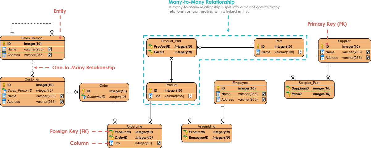
Let's break down what this diagram is showing us:
- Entities: We see familiar entities like
Customer,Order,Product, andSupplier. We also see more detailed ones likePart,Sales_Person, andEmployee. - Primary and Foreign Keys: Notice the "PK" and "FK" labels. In the
Ordertable,CustomerIDis an FK that links it back to theCustomertable. - One-to-Many Relationships: Look at the relationship between
CustomerandOrder. The line ends with a single hash nearCustomer(meaning "one") and a "crow's foot" symbol nearOrder(meaning "many"). This visually represents that one customer can have many orders. - Many-to-Many Solution: Find the
Product,Part, andSupplierentities. Notice theProduct_PartandSupplier_Parttables. These are associative entities. AProductis made of manyParts, and aPartcan be used in manyProducts. TheProduct_Parttable breaks this many-to-many relationship. The same logic applies toSupplierandPart.
Here is another example using a different common notation style (Chen notation), where attributes are shown as ovals. The underlying concepts are identical.

5. Advanced Topic: Handling Product Variations
Real-world inventory is often more complex. A single "product" (like a t-shirt) might come in different colors and sizes. Each unique combination (e.g., a "Medium, Blue T-Shirt") is a distinct item you need to track in your inventory with its own stock count (SKU).
Modeling this correctly is a common challenge that separates a basic schema from a robust one. How do you design an ERD for this? You need to separate the general product information from the specific, stock-tracked item.
eCommerce Product Database Design: Step-By-Step
This video on designing an e-commerce database gives a masterclass on modeling product variations. While the context is e-commerce, the inventory logic is identical and highly relevant.
Please watch the section from this point. The presenter starts by adding color, then size, and stock quantity. Pay close attention to the moment around 13:18 where they realize the product_item table is doing too much and decide to split it into two tables (product_item for color-specific info and product_variation for size/stock info). This is a professional-level refinement.
This process of refining your tables to reduce data duplication is called normalization, and it's a fundamental concept in database design. The key takeaway is that you often need to create more entities than you initially thought to model relationships correctly and efficiently. A good ERD helps you discover this before you start coding.
Conclusion
In this lesson, we moved from a simple list of entities to a structured, visual blueprint of our database. You learned how to sketch an ERD by defining entities, their attributes, and the crucial relationships that connect them.
Key Takeaways:
- ERDs are Database Blueprints: They are essential for planning your application's data architecture.
- Core Components: Every ERD is built from Entities (rectangles), Attributes (properties, including PKs and FKs), and Relationships (lines).
- Cardinality is Key: Understanding relationships as one-to-one, one-to-many, or many-to-many is crucial for accurate modeling.
- Associative Entities: Many-to-many relationships are resolved using a linking table (like
OrderLine) that turns one N:M relationship into two 1:N relationships. - ERDs Evolve: As you consider real-world complexities like product variations (size, color), your ERD will become more detailed to handle them gracefully, often through normalization.
In our next lesson, we will apply these skills to another domain you're interested in. We will sketch an ERD for an e-commerce store, focusing on entities like Product, Cart, Order, and User. This will allow us to practice these concepts again while modeling features specific to a customer-facing storefront.