Welcome to the next lesson in our exploration of ASME B31.3 design principles. In our previous sessions, we have carefully defined the operational boundaries for a piping system by establishing the design pressure and temperature, and we've learned to classify the forces acting on it into sustained, displacement, and occasional load categories. We now have the "demand" side of the equation: the conditions the pipe must withstand. Today, we turn to the "capacity" side: the inherent strength of the material itself.
This lesson focuses on one of the most fundamental parameters in the entire code: the basic allowable stress, denoted as . This value represents the maximum stress a material can safely handle under sustained loads at a given temperature. Understanding how this value is derived and where to find it is the cornerstone of all subsequent pressure design and stress analysis calculations. By the end of this lesson, you will be able to look up the correct allowable stress for a given material and design temperature directly from the ASME B31.3 tables.
The Foundation of Material Strength: The 'S' Value
Every calculation we will perform to check the integrity of a piping system—from wall thickness to flexibility analysis—relies on comparing a calculated stress to an allowable stress limit. The basic allowable stress, , is the parent value from which many of these limits are derived. For example, the allowable stress for sustained loads, , which we mentioned in the last lesson, is fundamentally equal to this value at the design temperature.
But where do these allowable stress values come from? They are not arbitrary numbers. They are the result of a conservative, safety-driven evaluation of a material's fundamental mechanical properties. Given your background in mechanical engineering, you'll find the logic behind these values familiar.
The following articles provide an excellent breakdown of the criteria ASME B31.3 uses to establish the allowable stress for common piping materials.
This guide from Centerway Steel clearly explains the logic behind the allowable stress rules and provides a direct, practical calculation for a common pipe material.
Please read the following sections: Start with the section "What Are the Basic Rules of ASME B31.3?". This part explains the core criteria for temperatures below the creep range. Next, review the worked example in the section "How Do We Calculate It for A106 Grade B Pipe?". This demonstrates the application of the rules. Finally, read the section "How Does High Temperature Change the Limits?" to understand the effect of temperature.
Allowable Pipe Stress Based on ASME B31.3 - Engineering Geek
This article from Engineering Geek offers a more formal list of the criteria, including those for high-temperature (creep) conditions, providing a comprehensive view.
Focus on these two parts: Read the bulleted list in the section "ASME B31.3 Allowable Stress for Piping Materials". This list formally states the basis for the allowable stress value, S. Review the explanation of how temperature affects carbon steel in the section "Allowable Stress VS Temperature in Different Materials".
Deriving the Allowable Stress: A Calculation Example
Let's synthesize what you've just read. For a typical carbon steel pipe like ASTM A106 Grade B operating at temperatures below the creep range (roughly below 400°C or 750°F), the basic allowable stress is defined as the lowest of the following values:
- 1/3 of the specified minimum tensile strength (UTS) at room temperature.
- 2/3 of the specified minimum yield strength (YS) at room temperature.
Let's perform the calculation for ASTM A106 Grade B, a material you will encounter constantly in process piping. From material specifications, we know:
- Specified Minimum Tensile Strength (UTS): 60,000 psi (60 ksi)
- Specified Minimum Yield Strength (YS): 35,000 psi (35 ksi)
Now, we apply the criteria:
Comparing the two results, the lower value is 20,000 psi (or 20.0 ksi). This is the basic allowable stress for this material at lower temperatures. The code effectively builds in a safety factor of 3 against ultimate failure.
As the articles noted, at higher temperatures, the material strength degrades. Above the creep threshold, the allowable stress is no longer based on tensile or yield strength but rather on long-term creep data, such as the stress required to produce a creep rate of 0.01% in 1,000 hours. This is why allowable stress values drop significantly at elevated temperatures.
From Theory to Practice: Using ASME B31.3 Table A-1
While understanding the basis of the 'S' value is crucial for a designer, you don't have to perform this calculation every time. The results of these evaluations for hundreds of materials are compiled in Appendix A of ASME B31.3. The primary table you will use is Table A-1 (for US Customary units) and Table A-1M (for SI units).
Let's find the value we just calculated.
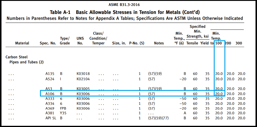
In the table above, find the material A106 with Grade B. Following that row to the right, you can see the columns for temperature. At a metal temperature of 100°F, the allowable stress listed is 20.0, which is 20.0 ksi or 20,000 psi. This perfectly matches the value we derived. You can also see that this value remains constant up to 650°F, after which it begins to decrease, reflecting the material's loss of strength at higher temperatures.
Now let's look at the same table in SI units, which is more common in modern international projects.

Let's find the allowable stress for the same A106 Grade B pipe, but this time for a design temperature of 400°C.
- Find the row for material A106, Grade B. In this table, it's on Line No. 31.
- Follow this row to the right until you reach the column for the metal temperature of 400°C.
- The value listed is 113 MPa.
This process of identifying the material and reading the corresponding stress value at the design temperature is a routine and critical task in piping design.
The following video clip shows how this 'S' value is plugged into a real design formula—in this case, for calculating minimum required wall thickness. This reinforces why finding the correct value is so important.
Minimum Required Thickness Calculation & Determine Pipe Schedule on ASME B31.3 - API 570 Exam
This short excerpt from a tutorial by I4I Academy shows the practical application of the allowable stress value in a B31.3 calculation.
Watch the segment from the variable explanation. The instructor explicitly points out that the 'S' value in the formula must be looked up in Table A-1 based on the material and design temperature. This is the exact process we are learning now.
Conclusion
In this lesson, we bridged the gap between material science and practical code application. You now understand not only how to find the basic allowable stress but also why it has the value it does. This foundational knowledge is essential for making sound engineering judgments.
Here are your key takeaways:
- The basic allowable stress () is the maximum stress a material can safely handle under sustained loads and is the basis for most other stress limits in ASME B31.3.
- For common steels below the creep range, is determined as the lower of 1/3 of the ultimate tensile strength or 2/3 of the yield strength.
- At elevated temperatures, allowable stress is governed by creep properties, causing its value to decrease significantly.
- The definitive source for these values is ASME B31.3 Table A-1 (US Customary) and Table A-1M (SI units), where you can look up for a specific material and design temperature.
You now have a firm grasp of the three core inputs for pressure design: design pressure, design temperature, and allowable stress. However, the 'S' value assumes a perfect, seamless pipe. As a welding engineer, you know that the reality of fabrication, especially welding, introduces factors that can affect the pipe's strength.
In our next lesson, we will address this by learning how to determine the weld joint quality factor (). This factor adjusts the allowable stress to account for the type of weld used in the pipe (e.g., seamless vs. ERW) and the level of non-destructive examination performed. This will be the final parameter needed before we can begin calculating pipe wall thickness.